blog

Hogar

blog

  • The Ultimate Guide to Ball Valves and How to Choose Them | GEKO Valve
    The Ultimate Guide to Ball Valves and How to Choose Them | GEKO Valve
    Oct 28, 2026
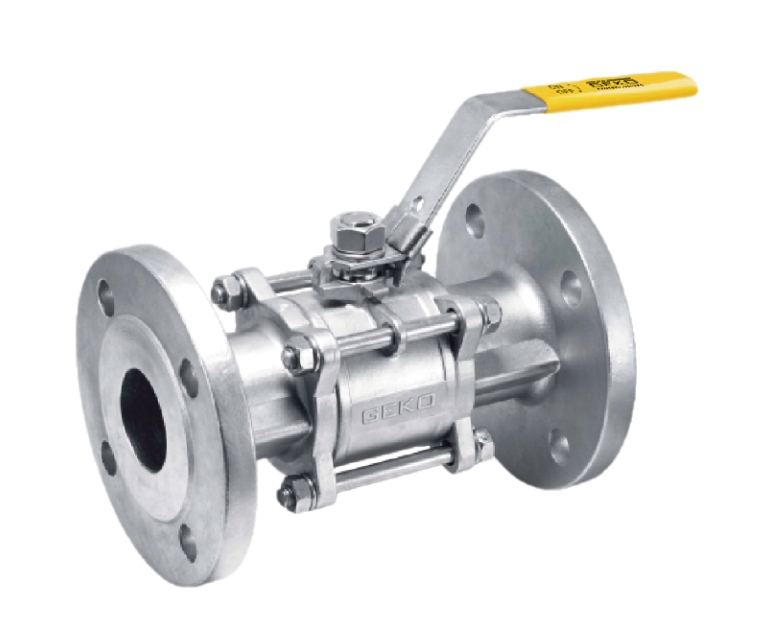
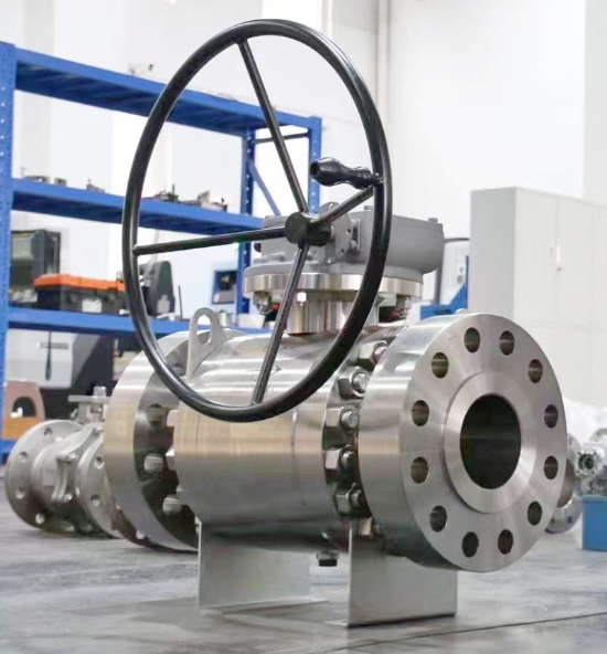
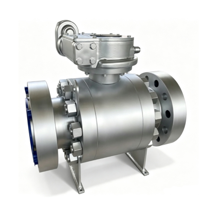
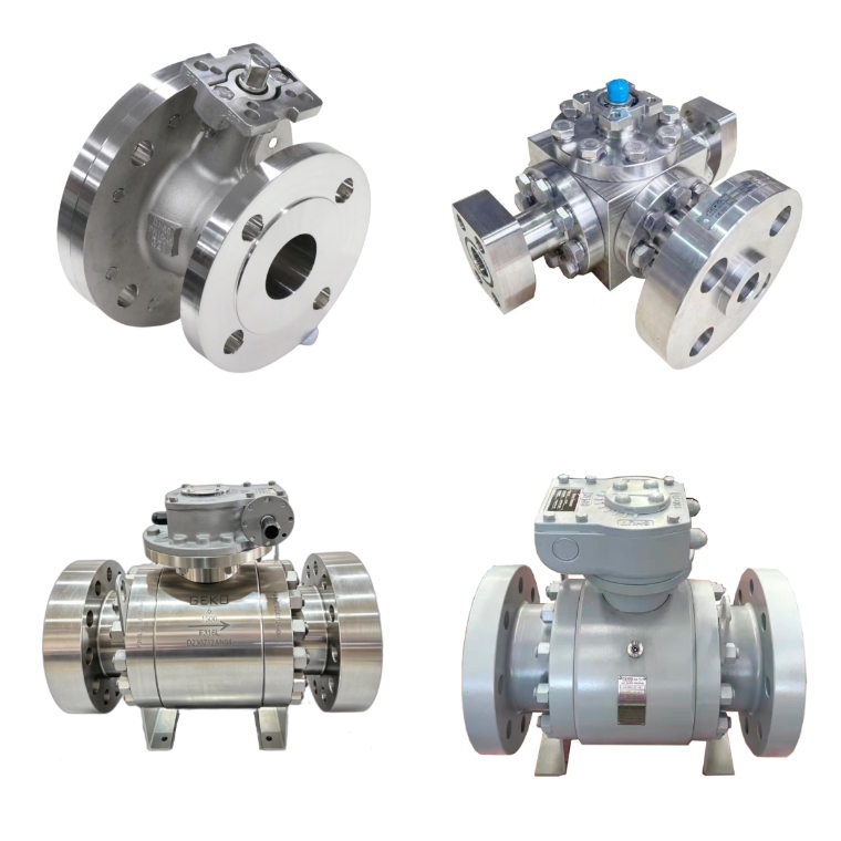
    The Ultimate Guide to Ball Valves and How to Choose Them | GEKO Valve Ball valves are among the most widely used quarter-turn fluid control devices across industrial piping systems. Known for fast operation, reliable sealing, low maintenance and compact structure, they serve critical isolation and flow regulation tasks in water treatment, oil & gas, chemical processing, power generation and many other sectors. This complete guide covers ball valve basics, common types, key specifications and practical selection rules to help you pick the right ball valve for your working conditions. What Is a Ball Valve? A ball valve uses a hollow, perforated rotating ball inside the valve body to control fluid flow. When the ball’s bore aligns with the pipeline, the valve opens and media passes through. Rotating the ball 90 degrees blocks the passage, shutting off flow. Most standard ball valves are designed for tight shut-off, though special designs support throttling service. GEKO Valve delivers a full lineup of ball valves built to deliver dependable sealing and long service life for industrial projects.   Common Types of Ball Valves Floating Ball Valve – The ball is not fixed by upper and lower trunnions. Fluid pressure pushes the ball against the downstream seat to form a seal. Ideal for medium and low pressure applications, simple structure and cost-effective. Trunnion Mounted Ball Valve – The ball is supported by fixed trunnions at top and bottom. Sealing force does not rely fully on line pressure. Suitable for high pressure, large size and heavy-duty industrial pipelines. Top Entry Ball Valve – Maintenance can be carried out directly on site without removing the whole valve from the pipe. Preferred for critical pipelines where shutdown and disassembly are costly. Side Entry (Split Body) Ball Valve – The body is split into two or more parts for easy assembly. Widely used for general industrial and water service. Full Port vs Reduced Port Ball Valve – Full port ball valves have a bore size matching the pipe inner diameter, minimizing flow resistance and pressure drop. Reduced port ball valves feature a smaller bore, lower cost and compact size for non-critical flow loss scenarios. Lined Ball Valve – Lined with PFA, PTFE or other corrosion-resistant materials, for handling strong acids, alkalis and aggressive chemical media. Key Components of a Ball Valve Valve Body: The main pressure-containing shell; common materials include WCB, A105, 304 stainless steel, 316 stainless steel, duplex steel and alloy steel. Ball: The rotating closure member, available in stainless steel, carbon steel, hard-faced alloy for abrasive service. Seat & Sealing Insert: PTFE, RPTFE, Viton, Devlon, metal seat for high temperature or fire-safe requirements. Stem: Transmits torque from the handle or actuator to the ball; anti-blowout stem design is a standard safety feature on GEKO Valve ball valves. Operator: Manual lever, gearbox, pneumatic actuator, electric motor operator (MOV) for automated control. Main Industrial Applications Oil and gas: wellhead isolation, pipeline transmission, refining and storage terminals Chemical industry: corrosive chemical transfer, batch processing and reactor isolation Water treatment: raw water, clean water, sludge and wastewater pipelines Power plants: cooling water, steam auxiliary systems and compressed air lines Food and beverage: sanitary ball valves for hygienic media Hydrogen and clean energy: low-leakage ball valves for hydrogen storage and transportation How to Choose the Right Ball Valve: Step-by-Step Checklist 1. Confirm Media Properties Identify the fluid: water, oil, gas, acid, alkali, slurry or hydrogen. Corrosive media require stainless steel or lined construction. Slurry service needs hard-faced balls and wear-resistant seats to avoid abrasion damage. The technical team at GEKO Valve can assist with material matching for challenging media. 2. Working Pressure and Temperature Match the valve pressure class (Class 150, 300, 600, 900 etc.) to your maximum operating pressure. Check temperature limits: soft seats work well at moderate temperatures, while metal-seated ball valves handle high temperature and fire-safe service. 3. Valve Size and Flow Requirement Select full port if low pressure drop is essential. Reduced port is acceptable when flow loss is not a concern. Confirm connection ends: flange, threaded, butt weld or socket weld to match your piping. 4. Operation Type Manual lever: simple, low cost, for infrequent operation Gear operated: for large size or high torque valves Pneumatic actuator: fast on/off, suitable for automatic control systems Electric actuator: ideal for remote control and slow switching 5. Sealing and Safety Requirements Soft seats provide bubble-tight shut-off for most general service. Metal-to-metal seats are selected for high temperature, fire-safe, abrasive or high cycling conditions. Fire-safe certification and low-emission stem packing are available for hazardous media. 6. Industry Standards Common standards include API 6D, ASME B16.34, ISO 17292. Confirm whether you need special tests such as fugitive emission test, hydrostatic test and cryogenic test. Advantages and Limitations of Ball Valves Advantages 90-degree quick open and close, easy operation Excellent tight shut-off performance Simple structure, fewer wearing parts, long service life Wide range of material options for different media Limitations Standard soft-seated ball valves are not recommended for continuous heavy throttling High temperature may degrade soft seat materials Trunnion and large-size ball valves come with higher cost Final Selection Tips Never choose a ball valve only by nominal size and pressure rating. Always evaluate media corrosion, temperature cycling, actuation frequency and safety codes. If you work with hazardous or high-value media, prioritize certified low-leakage and fire-safe designs. For long-term reliability, match body, ball and seat materials as a complete set rather than mixing incompatible materials. Reach out to GEKO Valve for technical support when you are unsure about your selection. Conclusion Ball valves are versatile, dependable fluid control components, but proper selection directly determines system safety and service life. This guide walks you through core types, construction, application scenarios and critical selection criteria. When you clarify your media, pressure, temperature, operation mode and standard requirements, you can efficiently narrow down the correct ball valve model for your piping project. Target Keywords GEKO ball valve, trunnion ball valve, floating ball valve, stainless steel ball valve, PTFE seat ball valve, fire safe ball valve, full port ball valve, industrial ball valve, low emission ball valve
    LEER MÁS
  • Ball Valve Materials Guide for Corrosion Resistance and Durability | GEKO Valve
    Ball Valve Materials Guide for Corrosion Resistance and Durability | GEKO Valve
    Oct 20, 2026
    Ball Valve Materials Guide for Corrosion Resistance and Durability Corrosion and premature wear are two leading causes of ball valve failure in chemical processing, offshore, water treatment, and oil & gas piping systems. Selecting the correct ball valve materials directly determines long-term durability, sealing integrity, safety, and total cost of ownership. A ball valve built with incompatible alloys or seat materials can suffer pitting, crevice corrosion, chemical attack, or seal degradation, leading to fugitive emissions, unplanned shutdowns, and expensive replacement. This GEKO Valve guide breaks down body, ball, liner, and seat materials by corrosion performance, service limits, and suitable industrial applications, helping engineers specify valves that last in aggressive process media. Why Corrosion Resistance and Material Durability Matter for Ball Valves Unlike generic piping components, ball valves contain wetted parts that stay in continuous contact with process fluids — acids, alkalis, brine, chlorides, solvents, and sour media. Even minor corrosion can lock the rotating ball, damage sealing surfaces, and break pressure containment. Durability does not only mean mechanical strength; it combines corrosion resistance, temperature stability, abrasion resistance, and resistance to cyclic operation. The optimal material balances chemical compatibility, pressure rating, temperature range, and project budget rather than defaulting to the most expensive superalloy.   Common Ball Valve Body Materials for Corrosive Service WCB Carbon Steel WCB is the standard cast carbon steel for general-purpose ball valves. It delivers high mechanical strength and pressure resistance but offers limited corrosion resistance. Carbon steel is suitable for clean oil, steam, natural gas, and non-corrosive water. In corrosive environments, WCB ball valves rely on internal PTFE or PFA lining to isolate the metal body from aggressive media. Without lining, carbon steel will rust rapidly in damp, acidic, or chloride-rich conditions. 304 / 316L Stainless Steel (CF8 / CF3M) 304 stainless steel works well for low-chloride fresh water, food-grade fluids, and mild alkaline solutions. 316L stainless steel adds molybdenum, greatly improving resistance to chloride ions, dilute acids, wastewater, and common organic solvents. The low-carbon 316L grade avoids intergranular corrosion after welding, making it the most widely specified stainless steel ball valve for moderate corrosion duties. It remains the baseline anti-corrosion choice for water treatment, pharmaceutical, and general chemical lines. 2205 and 2507 Duplex Stainless Steel Duplex stainless steel combines austenite and ferrite microstructures for superior chloride corrosion resistance and higher strength than 316L. 2205 duplex handles brine, brackish water, and moderate seawater service. 2507 super duplex offers outstanding pitting and stress corrosion cracking resistance for seawater desalination, coastal chemical plants, and produced water pipelines where standard 316L will fail over time.   High-Performance Alloys: Hastelloy C276, Monel 400, Inconel 625 Hastelloy C276 resists strong oxidizing acids, chlorine, hypochlorite, and mixed corrosive chemicals, widely used in chlor-alkali and fine chemical processes. Monel 400 provides excellent resistance to hydrofluoric acid and seawater. Inconel 625 is selected for high-temperature corrosive media and thermal fatigue conditions. These nickel-based superalloys deliver extreme corrosion protection but carry a much higher material cost and longer lead times. PTFE / PFA Lined Ball Valves Lined ball valves use a carbon steel or stainless steel shell with a continuous fluoropolymer liner covering all wetted surfaces. PTFE and PFA are nearly chemically inert against most concentrated acids, bases, and aggressive solvents. PFA offers better permeation resistance and higher-temperature stability than PTFE. Lined ball valves are a cost-effective alternative to exotic alloys for strong corrosive media at moderate pressure ranges. Ball and Seat Materials: The Critical Sealing Interface Body alloy protects the valve shell, but the ball and seat form the sealing interface that controls leakage and cycle life. Seat material failure is one of the most frequent durability issues in corrosive ball valves. Virgin PTFE: Universal chemical resistance, compatible with almost all corrosive media. Drawback: cold flow under sustained pressure, which can degrade sealing after long static hold periods. RPTFE (Reinforced PTFE): Filled with glass, carbon, or graphite to reduce creep and boost wear resistance while retaining broad chemical compatibility. It is the most popular upgrade over pure PTFE. PEEK: Excellent combination of corrosion resistance, high temperature capability, and mechanical durability for high-cycle and high-pressure chemical service. Viton / EPDM: Elastomer seats for specific media; Viton suits oils and hydrocarbons, EPDM works for hot water and weak acids. Both are limited against strong solvents and concentrated acids. Metal Seat with Stellite Coating: Hardened metal sealing surfaces for high temperature, abrasive slurry, and fire-safe service. Metal-sealed ball valves rely on alloy selection for corrosion resistance and do not provide bubble-tight shutoff like polymer seats. Key Selection Checklist for Corrosion Resistance & Durability Before finalizing ball valve materials, verify these application parameters: Full chemical composition of the process fluid, including trace chlorides, solids, and oxidizers Operating temperature and pressure, plus upset and thermal cycling conditions Flow velocity and abrasive particles that cause erosion wear Shutoff requirement: bubble-tight soft seat or fire-safe metal seat External environment: coastal salt spray, humid air, or underground burial Maintenance access and expected service life target Common Application Matching Summary Fresh water and mild chemical media → 316L ball valve with RPTFE seat. Seawater and brine → 2205 / 2507 duplex stainless steel. Concentrated acids and aggressive solvents → PFA-lined ball valve. Chlorine and mixed oxidizing chemicals → Hastelloy C276. High-temperature abrasive process → Stellite hard-faced metal seat paired with compatible body alloy. Final Thoughts Durable, corrosion-free ball valve performance comes from matching every wetted component to the process conditions, not just picking a single alloy. GEKO Valve supplies ball valves in carbon steel, stainless steel, duplex, nickel alloy, and PFA/PTFE lined configurations with a full range of seat and ball trim options. Proper material specification reduces corrosion-related failures and extends valve service life in demanding industrial piping systems.
    LEER MÁS
  • Ball Valve Materials: Pros and Cons for Industrial Applications | GEKO Valve
    Ball Valve Materials: Pros and Cons for Industrial Applications | GEKO Valve
    Oct 14, 2026
    Ball Valve Materials: Pros and Cons for Industrial Applications Selecting ball valve materials requires careful trade-offs between corrosion resistance, temperature tolerance, mechanical strength, cost and manufacturability. No single material works for every industrial process. Understanding the pros and cons of common ball valve body, ball and seat materials helps process engineers avoid premature failure, unexpected leakage and overspending on overly expensive alloys. This guide compares widely used materials for GEKO industrial ball valves to support faster, smarter valve specification. WCB Cast Carbon Steel & A105 Forged Carbon Steel Pros: High tensile strength, good performance under high pressure and elevated temperatures, affordable price, easy welding and machining. A105 forged carbon steel has denser grain structure, better impact resistance than cast WCB, ideal for critical high-pressure lines, steam and hydrocarbon service. Cons: Poor corrosion resistance. Carbon steel rusts rapidly when exposed to moisture, acids, chlorides and most corrosive chemicals. Not suitable for potable water, brine or continuous wet corrosive service. Impact performance drops sharply at cryogenic temperatures. SS304 / CF8 Stainless Steel Pros: Good general corrosion resistance for clean water and weak alkaline media, oxidation-resistant at moderate heat, easy to sanitize, cost-effective stainless option. It is widely accepted for sanitary, food and beverage, municipal water and general outdoor piping systems. Cons: Susceptible to pitting corrosion in chloride-containing environments such as seawater and brine. Poor resistance to strong acids. Not recommended for high-salinity or harsh chemical processes. SS316 / 316L (CF8M / CF3M) Stainless Steel Pros: Molybdenum addition improves chloride and mild acid resistance significantly. 316L low-carbon grade resists intergranular corrosion after welding. Versatile for chemical processing, food production, desalination pre-treatment and marine non-seawater circuits. It is the most popular stainless steel for corrosive industrial service. Cons: Still vulnerable to concentrated chloride, hot brine and strong reducing acids. Higher cost than SS304, and it cannot compete with duplex or nickel alloys for severe corrosion environments. 2205 Duplex Stainless Steel Pros: Combines austenitic and ferritic microstructure for high mechanical strength and excellent chloride pitting resistance. Outperforms 316 in brackish water, brine and low-to-moderate acid conditions. More economical than Hastelloy and other nickel alloys for seawater-related applications. Cons: Limited high-temperature operating range; it loses corrosion resistance at excessive heat. Less ductile than austenitic stainless steel and harder to machine. Not suitable for strong reducing acids. PFA / PTFE Lined Materials Pros: Almost universal chemical inertness against strong acids, alkalis and aggressive solvents. The metal shell provides structural strength while fluoropolymer lining isolates corrosive media. Perfect for harsh chemical processing where standard metals degrade quickly. Cons: Lining can be scratched by abrasive slurries. Not compatible with high-temperature steam. Temperature and pressure ratings are lower than solid metal valves, and lined valves are heavier and more expensive than carbon steel alternatives. Hastelloy C276, Alloy 20 and Monel Nickel Alloys Pros: Outstanding resistance to oxidizing acids, sour gas (H₂S), chlorine and many aggressive chemicals. Excellent resistance to stress corrosion cracking and localized pitting. These specialty alloys serve critical, high-risk processes where 316 and duplex steel fail. Cons: Very high raw material and machining costs. Long lead times are common. Nickel alloys are only justified for extreme corrosive conditions, making them impractical for standard water, oil or steam lines. Common Seat & Seal Materials: PTFE, FKM, Metal, PEEK PTFE: Pros — chemically inert, bubble-tight shutoff; Cons — prone to cold flow, limited high-temperature range. FKM (Viton): Pros — resistant to oils, fuels and hydrocarbons; Cons — incompatible with ketones and some strong acids. Metal seat: Pros — suitable for high temperature, abrasive media and frequent cycling; Cons — not bubble tight, higher torque requirement. PEEK: Pros — excellent wear and high-temperature resistance; Cons — premium pricing, limited availability. Quick Comparison Guidance Carbon steel works best for non-corrosive high-temperature steam and oil. SS304 fits clean, low-chloride water and sanitary light-duty service. SS316 balances performance and budget for general corrosive applications. 2205 duplex is the go-to for brine and high-chloride water. Lined valves handle aggressive chemicals, while nickel alloys are reserved for extreme corrosive process conditions. Closing Notes from GEKO Valve Material selection should never rely on cost alone. A cheaper valve that fails early will generate far higher downtime and maintenance costs. Share your medium, temperature, pressure and chemical concentration with GEKO’s engineering team to select a ball valve material that matches your industrial application perfectly.
    LEER MÁS
  • Which Ball Valve Material Is Best for Your Application? | GEKO Valve
    Which Ball Valve Material Is Best for Your Application? | GEKO Valve
    Oct 14, 2026
    Which Ball Valve Material Is Best for Your Application? Choosing the correct ball valve material is one of the most critical decisions for process reliability. Even a well-designed ball valve will fail prematurely if its body, ball and seat materials are incompatible with your fluid, temperature, pressure and chemical environment. With options ranging from WCB carbon steel and stainless steel to duplex steel, PFA lining and specialty alloys, engineers and procurement teams need a clear framework to match materials to their exact working conditions. This guide breaks down common ball valve materials, their strengths, limitations and ideal use cases to help you select the right GEKO ball valve for your system. Core Factors That Decide Ball Valve Material Before comparing materials, confirm four key process parameters. The fluid medium and chemical concentration determine corrosion risk. Operating temperature impacts material toughness, creep resistance and seal performance. Working pressure defines wall thickness and mechanical strength requirements. Additional factors include chloride content, abrasive particles, cyclic switching frequency and hygienic requirements for food or pharmaceutical service.     WCB Carbon Steel / A105 Forged Steel Ball Valves WCB cast carbon steel and A105 forged carbon steel are cost-effective, high-strength options for non-corrosive media. They perform reliably at elevated temperatures and suit steam, compressed air, fuel oil and natural gas pipelines in power plants, thermal systems and general oil & gas service. Carbon steel works well from -29°C up to around 425°C, but it rusts quickly when exposed to water, acids or chloride-rich fluids. It is not recommended for wet corrosive service, drinking water or chemical processing lines. SS304 (CF8) Stainless Steel Ball Valves SS304 stainless steel is the standard corrosion-resistant ball valve material for water treatment, clean water, weak alkaline fluids and general outdoor piping. It offers good oxidation resistance and excellent low-temperature toughness, making it popular for general industrial and sanitary applications. SS304 works for low-chloride water but struggles with saltwater, brine and concentrated chloride media, where pitting corrosion will develop over time. SS316 / 316L (CF8M / CF3M) Stainless Steel Ball Valves SS316 stainless steel includes molybdenum, which greatly improves resistance to chlorides, mild acids and many chemical solvents. It is the most widely specified stainless grade for chemical plants, desalination pre-treatment, food & beverage processing and marine non-seawater circuits. 316L low-carbon variants reduce intergranular corrosion after welding, preferred for long-term continuous chemical service. For most general corrosive industrial applications, SS316 is the default upgrade from SS304. 2205 Duplex Stainless Steel Ball Valves 2205 duplex stainless steel combines high mechanical strength and superior chloride pitting resistance. It outperforms 316 in brackish water, seawater, brine and moderate acid environments. Duplex ball valves are widely used in desalination, offshore auxiliary lines and mine water systems. It balances strength and corrosion resistance without moving to expensive nickel alloys, though it has narrower high-temperature limits than many stainless grades. PFA / PTFE Lined Ball Valves PFA and PTFE lined ball valves use a carbon steel or stainless steel pressure shell with a fluoropolymer lining that contacts the fluid. The lining is chemically inert against most strong acids, alkalis and aggressive solvents. These lined ball valves are the primary choice for harsh chemical processes where metallic alloys cannot survive. They are not suitable for high-temperature steam or abrasive slurries that can scratch the lining surface. Specialty Alloy Ball Valves: Hastelloy, Alloy 20, Monel For extreme corrosive conditions such as concentrated acids, sour gas, hydrogen sulphide and oxidising chemicals, GEKO supplies ball valves built from Hastelloy C276, Alloy 20 and Monel. These exotic alloys resist localized corrosion and stress cracking in environments that attack 316 and duplex steel. They carry higher material costs and are reserved for critical chemical, hydrogen and high-risk process applications. Seat & Seal Material Matching (Not Only Body Material) Body material alone cannot guarantee reliable shutoff. Seat materials must also match the process. PTFE seats deliver bubble-tight isolation for most clean fluids up to moderate temperatures. FKM (Viton) works for oils and hydrocarbons. Metal seats are selected for high temperature, abrasive media and frequent cycling. PEEK seats offer outstanding wear resistance for demanding cyclic service. A mismatch between seat material and medium is a common cause of leakage even when the valve body is correctly specified. Quick Application Reference Steam, oil, compressed air: WCB / A105 carbon steel Clean water, food-grade mild fluid: SS304 General chemical, low-chloride corrosive service: SS316 / 316L Seawater, brine, high-chloride water: 2205 duplex stainless steel Strong acids and aggressive chemicals: PFA lined ball valve Sour gas, concentrated corrosive media: Hastelloy or nickel alloy Final Recommendations from GEKO Valve The best ball valve material is always the one that balances corrosion resistance, temperature-pressure rating, service life and budget. Over-specifying exotic alloys increases unnecessary expense, while under-specifying leads to unplanned shutdowns and safety risks. If you are unsure about material compatibility for your process fluid, share your medium, temperature, pressure and concentration data with GEKO’s engineering team for a verified material recommendation.
    LEER MÁS
  • How Does a Butterfly Valve Open and Close? Full Operating Guide | GEKO Valve
    How Does a Butterfly Valve Open and Close? Full Operating Guide | GEKO Valve
    Oct 09, 2026
    How Does a Butterfly Valve Open and Close? Full Operating Guide Butterfly valves are the most widely used quarter-turn flow control devices in industrial and municipal piping systems. Many engineers and procurement specialists select industrial butterfly valves for their compact size and cost-saving advantages, yet few fully understand the complete mechanical process of how a butterfly valve opens and closes. Unlike linear-stroke gate valves and globe valves, butterfly valves rely on precise rotary motion to change pipeline flow status. This article clearly explains the opening and closing working process, mechanical logic of different valve designs, actuation modes, and sealing coordination principles. 1. Basic Open and Close Principle of Butterfly Valves The entire opening and closing action of a butterfly valve is completed through a 90-degree quarter-turn rotation. The core moving parts include the valve stem and internal butterfly disc. The stem receives torque from manual or automated actuators and drives the disc to rotate horizontally inside the pipeline bore, realizing full opening, full closing, and intermediate throttling states. Closing Process (90° → 0°): The disc gradually rotates perpendicular to the fluid flow direction, continuously narrowing the flow passage. When reaching 0 degrees, the disc completely presses against the valve seat, blocking the pipeline and achieving tight shutoff. Opening Process (0° → 90°): The disc rotates parallel to the fluid direction, gradually expanding the flow area. At 90 degrees, the disc is fully opened, minimizing flow resistance and allowing maximum fluid passage. This simple rotary operation is what makes wafer butterfly valves and lug butterfly valves so popular for large-bore piping. 2. Complete Mechanical Action Process   The opening and closing cycle follows a fixed mechanical transmission chain, ensuring accurate and stable operation: First, the operating device (lever, gearbox, pneumatic or electric actuator) outputs rotational torque. The torque is transmitted to the central valve stem through the driving shaft. The integrated stem and disc structure rotates synchronously without idle travel. During movement, the disc gradually separates from or compresses against the sealing seat. Finally, the mechanical limit device locks the angle to complete opening or closing positioning. 3. Different Opening & Closing Logic by Valve Structure Concentric and offset butterfly valves have obvious differences in opening and closing friction, which directly affects service life and operating stability: 3.1 Concentric Butterfly Valve Operation Concentric butterfly valves have overlapping centers of the stem, disc, and pipeline. During every opening and closing stroke, the disc keeps continuous contact and friction with the seat. The operation is simple and cost-effective, suitable for low-frequency switching of conventional water treatment and HVAC pipelines. 3.2 Triple Offset Butterfly Valve Zero-Friction Operation Triple offset butterfly valves adopt a three-dimensional offset structure. During the opening process, the disc instantly separates from the seat without friction. During closing, the disc only contacts the seat at the final locking position. This zero-friction opening and closing mechanism greatly reduces seat wear, making this style of heavy duty butterfly valves suitable for high-temperature, high-pressure, and frequent switching industrial pipelines. 4. Sealing Coordination During Opening and Closing Different sealing types match different opening and closing mechanical characteristics: 4.1 Soft Seated Butterfly Valve Soft seated butterfly valves with EPDM or NBR seats rely on elastic compression to achieve zero leakage when fully closed. During closing, the disc gently squeezes the elastic seat to fill tiny gaps. During opening, the elastic seat resets automatically. This flexible sealing opening and closing mode ensures bubble-tight shutoff for clean water and gas media. 4.2 Metal Seated Butterfly Valve Metal seated butterfly valves adopt precision metal-to-metal matching. The opening and closing process realizes rigid mechanical fitting and separation. With high wear resistance and temperature resistance, they maintain stable switching performance in harsh working conditions such as high-temperature steam and abrasive slurry. 5. Opening and Closing Modes of Automated Butterfly Valves Modern industrial pipelines use automated butterfly valves to realize intelligent opening and closing control: Pneumatic Butterfly Valve: Driven by compressed air, it completes fast opening and closing strokes in seconds. With explosion-proof advantages, it is widely used in chemical and petrochemical pipeline switching. Electric Butterfly Valve: Driven by electric actuators, it features stable speed, precise angle positioning, and remote signal control. It supports delayed opening/closing and intermediate positioning, suitable for intelligent pipeline systems. Manual Butterfly Valve: Operated by lever or gear handwheel, it realizes on-site manual opening and closing, economical and convenient for low-frequency operation scenarios. 6. Common Opening & Closing Faults and Causes Valve jamming: Caused by sediment deposition, seat aging, or insufficient actuator torque Incomplete closing and leakage: Disc offset, seat wear, or foreign matter blocking the sealing surface Slow opening and closing speed: Pneumatic air pressure insufficiency or electric actuator parameter deviation 7. GEKO Valve Precise Opening & Closing Performance All GEKO butterfly valves adopt optimized rotary motion structure, ensuring flexible, smooth, and accurate opening and closing actions. Our full product range including wafer, lug, soft seat, metal seat, and triple offset butterfly valves achieves zero-friction switching, stable sealing, and long service life. Automated modulating butterfly valves support arbitrary angle opening and closing, meeting isolation and throttling control requirements of modern industrial piping systems.
    LEER MÁS
  • What Is the Role of a Butterfly Valve in Piping Systems? | GEKO Valve
    What Is the Role of a Butterfly Valve in Piping Systems? | GEKO Valve
    Oct 09, 2026
    What Is the Role of a Butterfly Valve in Piping Systems? Industrial and municipal piping networks transport liquids, gases and slurries across vast facilities, requiring reliable flow control hardware to keep operations safe and predictable. As a popular quarter-turn valve, the butterfly valve performs multiple core functions within piping systems. Its compact build, lightweight body and flexible operating modes make it a go-to choice for many pipeline designs, from large water mains to chemical processing lines. This article breaks down the key roles butterfly valves play in piping systems and where their strengths shine. 1. Fluid Isolation for Pipeline Maintenance & Emergency Shutoff One primary role of a butterfly valve is positive isolation. When a pipe segment, pump or downstream equipment needs inspection or repair, operators close the butterfly valve to fully cut off fluid flow. In emergency scenarios such as pipeline overpressure or equipment failure, it can rapidly shut down the line to prevent spillage and system damage. Lug and flange butterfly valves are commonly used for isolation duties, with PTFE or EPDM seats delivering tight shutoff performance. 2. Flow Throttling and Flow Regulation Beyond simple on/off service, butterfly valves are widely used for throttling flow. By rotating the disc to partial opening positions, the valve adjusts the cross-sectional flow area, controlling the volume and velocity of fluid moving through the piping. This function helps stabilize pressure and maintain consistent flow rates for processes like water distribution, HVAC circulation and chemical transfer. Note that precise throttling requires proper material selection to avoid disc erosion from high-speed media. 3. Pressure Control and Surge Mitigation Butterfly valves assist in managing pipeline pressure. Gradual opening or closing can moderate pressure spikes caused by pump start-up and shutdown. In large-diameter piping systems, slow-actuated butterfly valves help reduce water hammer effects that may damage pipe fittings and instruments. Pneumatic or electric actuators are often paired with butterfly valves for automated pressure regulation in modern piping networks.   4. Diversion and Flow Direction Switching In multi-branch piping layouts, sets of butterfly valves work together to divert fluid to different branches. For example, in water treatment plants, they switch flow between filter banks, or in district heating systems, they redirect hot water to different building zones. This eliminates the need to shut down the entire piping system when rerouting process media. 5. Backflow Prevention (Auxiliary Function) While butterfly valves are not dedicated check valves, properly specified butterfly valves can help limit unwanted reverse flow in certain low-risk piping applications. For critical backflow protection, they are usually combined with dedicated check valves as part of a complete piping safety assembly. Key Benefits of Butterfly Valves for Piping Networks Space-saving design: Much thinner than gate or globe valves, ideal for tight pipe rack installations Light weight: Reduces structural load on pipe supports, lowering overall project cost Fast quarter-turn operation: Manual lever, gear, pneumatic or electric actuation options available Wide size range: Works for both small process lines and large diameter main pipelines Corrosion-resistant options: Lined butterfly valves available for corrosive chemical media Selection Tips According to Piping Roles Choose resilient seated butterfly valves for water and wastewater isolation tasks. For corrosive fluids, PTFE lined butterfly valves are recommended. If automatic control is required, specify pneumatic or electric actuators to integrate with plant control systems. Confirm pressure class, flange standard and seat material to match your piping medium and operating temperature. Summary Within piping systems, butterfly valves serve five major purposes: fluid isolation, flow throttling, pressure management, flow diversion and auxiliary backflow control. Thanks to their compact footprint and versatile actuation choices, butterfly valves deliver dependable flow control across water, chemical, power and HVAC piping networks. Selecting the correct butterfly valve design ensures stable, long-term pipeline operation and reduces unplanned downtime.
    LEER MÁS
  • How Do Butterfly Valves Work in Water Treatment Plants? | GEKO Valve
    How Do Butterfly Valves Work in Water Treatment Plants? | GEKO Valve
    Oct 09, 2026
    How Do Butterfly Valves Work in Water Treatment Plants? Water treatment facilities rely on stable, cost-effective flow control equipment to manage raw water intake, chemical dosing, filtration, disinfection and effluent discharge. Butterfly valves are widely preferred across all stages of water treatment thanks to their compact size, fast quarter-turn operation, light weight and competitive pricing. Compared with bulky gate valves, butterfly valves save installation space and reduce structural load for large-diameter pipelines commonly seen in water plants. This article explains how butterfly valves function in key water treatment processes and their practical operational advantages. Core Working Principle for Water Treatment Service A butterfly valve uses a circular disc mounted on a central shaft. When the valve rotates 90 degrees, the disc turns parallel or perpendicular to fluid flow. At the fully open position, water flows with minimal resistance; at the closed position, the disc presses against the seat to shut off flow. Between open and closed angles, partial rotation enables throttling for controlled water flow rates. Most water treatment butterfly valves use resilient rubber seats such as EPDM, delivering bubble-tight shutoff for clean and wastewater media.   Typical Applications Inside Water Treatment Plants 1. Raw Water Intake & Pump Station Butterfly valves are installed at intake lines and pump outlets to isolate pipelines during pump maintenance. They quickly cut off raw water from rivers, lakes or reservoirs, protecting downstream filtration units. Large wafer or lug type butterfly valves are commonly selected here due to easy installation between pipe flanges. 2. Coagulation, Flocculation and Sedimentation Tanks Within sedimentation basins, butterfly valves regulate flow between treatment chambers. Operators adjust the disc angle to balance water velocity, supporting stable floc formation and solid settling. Manual or gear-operated versions are widely used for frequent on-off and moderate throttling tasks. 3. Filtration Systems Sand filters and activated carbon filter banks use butterfly valves to switch between filtration and backwash cycles. The valves isolate individual filter units so one tank can undergo backwashing without shutting down the whole treatment line. EPDM seats resist wear from periodic flushing and particle-laden water. 4. Disinfection and Chemical Dosing Lines For chlorine, sodium hypochlorite or pH adjustment chemical pipelines, lined butterfly valves prevent corrosion from chemical additives. They provide reliable isolation for maintenance of dosing skids and mixing chambers. 5. Effluent Discharge and Wastewater Outlet Before treated water is released, butterfly valves control discharge flow and act as emergency shutoff devices. Lug style butterfly valves are often chosen for end-of-line service, allowing blind flange isolation when required. Key Selection Considerations for Water Treatment Butterfly Valves Seat material: EPDM is standard for clean water; choose stronger wear-resistant seats for wastewater with suspended solids Body material: Ductile iron is the mainstream cost-effective option for water projects Actuation: Manual gearbox for occasional operation; pneumatic or electric actuators for automated plant SCADA control Pressure rating: Match pipeline working pressure and surge pressure from pump startup and shutdown Valve type: Wafer butterfly valves for compact installation; lug butterfly valves for dead-end service Advantages of Butterfly Valves in Water Plants Their lightweight design lowers pipeline support costs, while fast quarter-turn operation speeds up emergency shutdown. They are easy to automate for modern smart water plants, and require less maintenance than many alternative valves. The main limitation is that standard resilient seated butterfly valves are not suitable for high-pressure steam or highly abrasive heavy slurry, which needs other valve solutions. Summary From raw water intake through filtration, chemical treatment to final discharge, butterfly valves serve as versatile flow isolation and throttling components across the full water treatment workflow. Properly sized butterfly valves with suitable seat and body materials help water plants maintain stable operation, reduce downtime and cut overall project and maintenance costs.
    LEER MÁS

  • What Is a Butterfly Valve and What Are Its Key Components? | GEKO Valve
    What Is a Butterfly Valve and What Are Its Key Components? | GEKO Valve
    Sep 29, 2026
      What Is a Butterfly Valve and What Are Its Key Components? A butterfly valve is a popular quarter-turn flow control device widely used in municipal and industrial piping systems to regulate, throttle, or completely shut off fluid flow. Its slim, lightweight design makes it far more space-saving than ball valves or gate valves, especially for large-diameter pipelines. Many new buyers and plant engineers want to understand exactly what a butterfly valve is and how each internal part works together to deliver reliable performance. This article breaks down the definition, core function, and all key components of a butterfly valve.   Definition and Core Function of a Butterfly Valve At its simplest, a butterfly valve controls fluid by rotating a circular disc inside the pipeline. A 90-degree rotation switches the valve between fully open and fully closed positions. It can also stay at intermediate angles for throttling flow. Wafer butterfly valves and lug butterfly valves are the two most common body styles, while offset designs like triple offset butterfly valves handle demanding high-temperature and high-pressure applications. Butterfly valves work with water, air, gas, and many chemical media across water treatment, HVAC, power, and chemical processing industries. Key Components of a Butterfly Valve 1. Valve Body The valve body forms the main pressure-containing shell and connects to the pipeline. Wafer-style bodies fit between two pipe flanges without bolt lugs. Lug bodies have threaded lugs built into the valve to hold flanges securely. Heavy-duty metal seated butterfly valves use cast iron, ductile iron, stainless steel, or alloy steel bodies to withstand harsh working environments. 2. Butterfly Disc The disc is the circular plate inside the body that blocks or allows fluid passage. It rotates with the valve stem. The disc shape directly impacts flow resistance. Concentric valves use a flat disc; double offset and triple offset valves use contoured discs to reduce seat friction during rotation. For corrosive media, discs are coated or made from stainless steel to extend service life. 3. Valve Stem The stem is a shaft that passes through the valve body and attaches firmly to the disc. It transfers torque from the actuator or handwheel to rotate the disc. Most stems are made of high-strength stainless steel to resist torsion and corrosion. Many designs use a one-piece stem and disc connection to eliminate play and improve control precision. 4. Seat / Sealing Ring The seat creates the sealing contact surface between the disc and valve body. Soft seated butterfly valves use elastomer seats such as EPDM or PTFE to achieve bubble-tight shutoff for clean media. Metal seated versions use metal-to-metal sealing surfaces, suited for high temperature, abrasive, or steam media where rubber seats cannot survive.   5. Stem Seals & Gaskets Stem seals prevent fluid leakage along the stem where it exits the valve body. Packing rings or O-rings form the primary barrier. They are critical to prevent fugitive emissions, especially for chemical and oil & gas applications. 6. Actuator / Operating Unit The actuator supplies torque to turn the stem and disc. Manual versions use a handwheel or lever. Pneumatic butterfly valves use compressed air for fast on/off or modulating control. Electric butterfly valves allow remote automated operation and precise flow adjustment. Positioners can be fitted to modulating actuators to maintain exact disc angles. How These Components Work Together When the actuator turns the valve stem, the disc rotates inside the body. In closed position, the disc presses against the seat to block fluid. When opened, the disc turns parallel to flow so media can pass through. All parts must be properly matched to the working pressure, temperature, and medium. A mismatch in seat or disc material will quickly cause leakage and premature failure. GEKO Valve Butterfly Valve Range GEKO Valve supplies complete butterfly valve assemblies with high-quality components. Our range includes soft seated and metal seated, concentric, double offset and triple offset butterfly valves, available in wafer, lug, flanged designs with manual, pneumatic or electric actuators for industrial and municipal projects worldwide. 9 Core SEO Keywords: Wafer Butterfly Valve, Lug Butterfly Valve, Triple Offset Butterfly Valve, Soft Seated Butterfly Valve, Metal Seated Butterfly Valve, Pneumatic Butterfly Valve, Electric Butterfly Valve, Automated Butterfly Valve, Heavy Duty Butterfly Valve
    LEER MÁS
  • How Does a Butterfly Valve Control Fluid Flow? Complete Working Guide | GEKO Valve
    How Does a Butterfly Valve Control Fluid Flow? Complete Working Guide | GEKO Valve
    Sep 29, 2026
      How Does a Butterfly Valve Control Fluid Flow? Complete Working Guide Butterfly valves are widely recognized as the most cost-effective and space-efficient fluid control devices for municipal and industrial pipelines. Unlike ball valves that provide full straight-line flow or gate valves designed only for full open or full closed isolation, industrial butterfly valves feature unique rotary disc mechanics that enable flexible fluid management. Many system designers and plant operators wonder: how does a butterfly valve control fluid flow accurately and stably? This guide explains the full flow control mechanism, different working states of butterfly valves, structural differences between product types, and practical flow control performance in modern piping systems. 1. Basic Fluid Control Principle of Butterfly Valves The core fluid control method of a butterfly valve relies on a90-degree quarter-turn rotary disc. Installed vertically in the pipeline center, the butterfly disc rotates along the valve stem to change the effective flow area inside the pipe. By adjusting the disc angle, the valve precisely changes flow resistance, fluid velocity, and pipeline pressure, thereby realizing three core flow control functions: full flow passage, partial throttling, and complete fluid shutoff. This simple and reliable rotary flow control method is the key reason why wafer butterfly valves, lug butterfly valves, and offset butterfly valves are widely used in large-diameter water, gas, and low-viscosity process fluid pipelines. 2. Three Core Flow Control States 2.1 Full Flow Open State When the disc rotates 90 degrees and is parallel to the fluid direction, the pipeline reaches maximum flow capacity. Although the disc remains inside the pipeline, the streamlined disc structure minimizes flow resistance. In this state, the industrial butterfly valve allows unrestricted fluid transmission, suitable for long-term circulating pipeline operation and maximum flow supply scenarios. 2.2 Precise Throttling and Flow Regulation State The biggest advantage of butterfly valves in fluid control is their excellent throttling performance. When the disc stays at any angle between 20% and 70% opening, it forms an adjustable shielding area inside the pipeline. The larger the shielding area, the higher the flow resistance and the lower the fluid flow rate. Modulating butterfly valves with electric or pneumatic actuators can maintain stable opening angles, realizing continuous and accurate flow balancing, pressure adjustment, and fluid distribution control for industrial systems.   2.3 Full Closed Fluid Shutoff State When the disc rotates to 0 degrees and is completely perpendicular to the fluid flow, the disc closely fits the valve seat to block the entire flow passage. Soft seated butterfly valves use elastic seat deformation to achieve bubble-tight zero leakage for clean media, while metal seated butterfly valves rely on precision metal fitting to block high-temperature, high-pressure and abrasive fluids, achieving reliable pipeline isolation and fluid cut-off. 3. How Different Butterfly Valve Types Optimize Flow Control Different butterfly valve structures deliver completely different fluid control effects, adapting to diverse industrial working conditions: 3.1 Concentric Butterfly Valves for General Flow Control Concentric butterfly valves feature coincident stem, disc and pipeline centers, providing stable basic flow regulation and isolation. They are ideal for conventional water treatment, HVAC, and fire protection pipelines with normal temperature and low pressure, offering economical and practical fluid control performance. 3.2 Double and Triple Offset Butterfly Valves for Heavy-Duty Flow Control Triple offset butterfly valves and double offset butterfly valves adopt a unique offset structure. The disc avoids friction with the seat during rotation, ensuring smooth and stable angle adjustment even under high pressure and high temperature. These heavy duty butterfly valves provide precise flow control for steam, flue gas, corrosive chemical media, and high-cycle industrial process pipelines. 3.3 Wafer vs Lug Type Flow Control Features Wafer butterfly valves feature ultra-thin bodies with low flow resistance, suitable for compact pipeline systems requiring stable large-flow control. Lug butterfly valves support unilateral pipeline disassembly while maintaining system flow control safety, facilitating segmented pipeline maintenance without affecting the overall fluid system. 4. How Actuators Support Accurate Fluid Control Stable fluid control cannot be achieved by the valve body alone; the actuator determines control accuracy and automation level: Manual Butterfly Valves: Realize simple on-site flow adjustment and pipeline isolation, suitable for low-frequency control scenarios. Pneumatic Butterfly Valves: Equipped with positioners to correct angle deviation, maintaining stable flow rate under fluctuating pipeline pressure, ideal for explosion-proof industrial fluid systems. Electric Automated Butterfly Valves: Support remote signal adjustment and proportional flow control, matching intelligent industrial systems to realize automatic fluid management and precise flow distribution. 5. Key Advantages of Butterfly Valve Fluid Control Achieve dual functions of fluid isolation and flow throttling with a single valve device Suitable for large-diameter pipeline flow control with low cost and small installation space Smooth rotary operation ensures stable fluid adjustment without pipeline surge Multiple product types adapt to clean, corrosive, high-temperature and abrasive fluid media Support manual and automatic intelligent fluid control for modern industrial systems 6. GEKO Valve Reliable Fluid Control Butterfly Valve Solutions GEKO Valve provides a full range of high-performance butterfly valves for precise industrial fluid control. Our product lineup includes soft seated and metal seated butterfly valves, concentric and triple offset butterfly valves, wafer and lug type butterfly valves, as well as manual, pneumatic and electric automated butterfly valves. All products deliver stable flow regulation, reliable shutoff performance and long service life, providing accurate and efficient fluid control solutions for water treatment, HVAC, chemical, power, and municipal engineering systems. 9 Core SEO Keywords: Industrial Butterfly Valve, Triple Offset Butterfly Valve, Soft Seated Butterfly Valve, Metal Seated Butterfly Valve, Wafer Butterfly Valve, Lug Butterfly Valve, Modulating Butterfly Valve, Heavy Duty Butterfly Valve, Automated Butterfly Valve
    LEER MÁS
  • ¿Cuál es el mecanismo de funcionamiento de una válvula de mariposa? | Válvula GEKO
    ¿Cuál es el mecanismo de funcionamiento de una válvula de mariposa? | Válvula GEKO
    Sep 21, 2026
     ¿Cuál es el mecanismo de funcionamiento de una válvula de mariposa?Las válvulas de mariposa son una de las válvulas de control de cuarto de vuelta más versátiles utilizadas en los sistemas de tuberías industriales y municipales modernos. Si bien la mayoría de los ingenieros están familiarizados con la conmutación rápida y la estructura compacta de válvulas de mariposa industrialesMuchos desconocen por completo el mecanismo de funcionamiento mecánico que permite un aislamiento de fluidos fiable, resistencia a la presión y modulación precisa del flujo en los distintos tipos de válvulas de mariposa. A diferencia de las válvulas de bola, que se basan en el sellado con bolas esféricas, o las válvulas de compuerta, que utilizan un movimiento vertical, las válvulas de mariposa emplean una estructura mecánica única de disco rotatorio. Este artículo analiza en profundidad el mecanismo de funcionamiento mecánico completo de las válvulas de mariposa, incluyendo la transmisión de par, la lógica de movimiento del disco, la mecánica de sellado de las válvulas de mariposa con asiento blando y metálico, los principios de funcionamiento de compensación y la coordinación del actuador para válvulas de mariposa automatizadas.1. Descripción general del mecanismo de funcionamiento mecánicoTodo el mecanismo de funcionamiento de una válvula de mariposa se basa en transmisión mecánica rotativa y adaptación de la dinámica de fluidosEl actuador genera un par de torsión que se transmite a través del vástago de la válvula para accionar el disco de mariposa interno, el cual realiza una rotación de 90 grados en un cuarto de vuelta. Al modificar el ángulo del disco dentro del conducto, la válvula cambia el área de la sección transversal del flujo, logrando así tres funciones mecánicas principales: corte del fluido, paso de flujo completo y regulación de estrangulamiento intermedio. La estructura mecánica completa presenta menos piezas de transmisión, una lógica de movimiento más simple y una respuesta más rápida que las válvulas industriales de múltiples carreras.2. Mecanismo de transmisión mecánica principal La transmisión de par es la principal fuente de energía para el funcionamiento de la válvula de mariposa. La cadena de transmisión mecánica completa consta de un actuador, un vástago de válvula, un pasador del eje y un disco de mariposa, lo que permite una conversión de potencia y una salida de movimiento precisas.Cuando el actuador recibe una señal de apertura o cierre, genera un par de torsión y lo transmite al vástago vertical de la válvula. El vástago se fija al disco de mariposa mediante pasadores de precisión, lo que elimina la rotación en vacío y garantiza un movimiento angular síncrono. El vástago cuenta con manguitos de alta precisión y juntas de estanqueidad para reducir la fricción, asegurando una rotación flexible y estable sin atascos. Este mecanismo de transmisión mecánica convierte la energía eléctrica, neumática o manual en rotación mecánica, completando las acciones de apertura y cierre de la válvula de manera eficiente.3. Mecanismo mecánico de control de flujo de discoEl disco de mariposa es el componente clave del control de fluidos, y su desplazamiento angular determina directamente el estado del flujo en la tubería. Los diferentes ángulos de apertura corresponden a estados de control de flujo mecánico completamente distintos.En la posición cerrada de 0 grados, el disco es completamente perpendicular a la dirección del fluido, formando una barrera total contra el medio. Bajo la acción de la presión del medio, el disco se ajusta firmemente al asiento de la válvula para lograr un sellado por compresión mecánica. En la posición totalmente abierta de 90 grados, el disco es paralelo a la dirección del fluido, minimizando la resistencia al flujo y permitiendo el paso máximo del mismo. En cualquier ángulo entre 0 y 90 grados, el disco forma una estructura de estrangulamiento superpuesta con el diámetro de la tubería, utilizando la oclusión mecánica para modificar la velocidad y la presión del flujo, logrando así una regulación continua del mismo.4. Mecanismo de sellado mecánico (sello blando y sello duro)El funcionamiento fiable de las válvulas de mariposa se debe a dos mecanismos de sellado mecánico diferentes, aplicables a distintas condiciones de trabajo industriales: 4.1 Mecanismo de sellado por compresión elástica (asiento blando)Válvulas de mariposa con asiento blando Se utilizan asientos de polímero elástico como EPDM y Viton. Durante el cierre, el disco comprime mecánicamente el asiento elástico, produciendo una microdeformación elástica. El asiento deformado rellena los pequeños huecos mecánicos entre el borde del disco y el cuerpo de la válvula, logrando un sellado hermético. Este mecanismo mecánico de compensación elástica se adapta a las pequeñas tolerancias de mecanizado y a las variaciones de presión en la tubería, garantizando un cierre hermético de las válvulas de mariposa con asiento blando en condiciones normales de temperatura y baja presión.4.2 Mecanismo de sellado de lapeado mecánico de precisión (asiento metálico)Válvulas de mariposa con asiento metálico Adopta un mecanismo de sellado rígido metal-metal. Tras un mecanizado de precisión y un pulido espejo, el disco y el asiento forman un par de sellado de alta precisión. Gracias al contacto mecánico rígido y a la fuerza de autoajuste por presión media, la válvula logra un sellado estable en condiciones de trabajo de alta temperatura, alta presión y abrasión. Esta estructura de sellado mecánico no presenta problemas de deformación por envejecimiento y permite un funcionamiento industrial prolongado y de alto ciclo en válvulas de mariposa de servicio pesado.5. Válvula de mariposa descentrada con mecanismo mecánico de fricción cero.Las válvulas de mariposa concéntricas y descentradas presentan diferencias fundamentales en su lógica de funcionamiento mecánico, lo que determina su vida útil y su resistencia a la presión.Las válvulas de mariposa concéntricas presentan un centro completamente coincidente del vástago, el disco y la tubería. El disco mantiene una fricción mecánica continua con el asiento durante cada ciclo de apertura y cierre, lo que provoca un fácil desgaste del asiento. En contraste, viajeel desplazamiento válvulas de mariposa Las válvulas de mariposa de doble desplazamiento adoptan una estructura mecánica de desplazamiento espacial. En la etapa inicial de rotación, el disco se separa automáticamente del asiento de sellado sin contacto por fricción. Solo en el ángulo de cierre final el disco entra en contacto con el asiento para su posicionamiento y sellado. Este mecanismo de operación mecánica sin fricción reduce considerablemente el desgaste de los componentes, mejora la durabilidad de la válvula y se adapta a las condiciones de trabajo de conmutación frecuente y de alta exigencia de las válvulas de mariposa de desplazamiento.6. Mecanismo de coordinación automatizada de actuadoresLos distintos actuadores conforman diferentes mecanismos de funcionamiento automático, adaptados a los modernos sistemas inteligentes de tuberías:Mecanismo de válvula de mariposa neumáticaConvierte la energía de la presión del aire comprimido en par de torsión de rotación mecánica, ofreciendo una acción rápida y un rendimiento mecánico a prueba de explosiones, adecuado para entornos industriales peligrosos.Mecanismo de válvula de mariposa eléctricaUtiliza un accionamiento por motor y amplificación de par mediante reductor para lograr un posicionamiento angular preciso, compatible con el control remoto por señal y la regulación proporcional.Mecanismo de válvula de mariposa manual: Se basa en la entrada de par mecánico manual, tiene una estructura de transmisión simple, lo que garantiza un funcionamiento estable y fiable a baja frecuencia.7. Ventajas industriales del mecanismo mecánico de la válvula de mariposaLa estructura de operación mecánica única dota a industrial válvulas de mariposa Con ventajas industriales insustituibles: su diseño mecánico compacto ahorra espacio de instalación para válvulas de mariposa tipo wafer y lug, su sencilla estructura de transmisión reduce las tasas de fallo, su mecanismo de compensación de fricción cero prolonga la vida útil de las válvulas de mariposa de triple compensación, y su desplazamiento angular flexible permite la doble función de aislamiento y regulación en válvulas de mariposa modulantes. Estas características mecánicas convierten a los distintos tipos de válvulas de mariposa en la solución preferida para sistemas de control de fluidos industriales y municipales de gran diámetro.8. Diseño mecánico de alta precisión de las válvulas GEKOGEKO Valve optimiza el mecanismo de operación mecánica interna de todas las válvulas de mariposa industriales. Mediante fundición de precisión, mecanizado CNC y tecnología de pulido espejo, nuestras válvulas de mariposa tipo wafer, con orejetas, con asiento metálico y con asiento blando ofrecen una transmisión de par uniforme, rotación flexible, posicionamiento preciso del disco y un sellado estable. Nuestra completa gama de productos, que incluye válvulas de mariposa concéntricas, de doble desplazamiento y de triple desplazamiento, satisface plenamente los requisitos de operación mecánica de diferentes tuberías industriales de baja, media y alta presión.9 palabras clave SEO principalesVálvula de mariposa industrial, válvula de mariposa de triple desplazamiento, válvula de mariposa de asiento blando, válvula de mariposa de asiento metálico, válvula de mariposa tipo wafer, válvula de mariposa con orejetas, válvula de mariposa modulante, válvula de mariposa de alta resistencia, válvula de mariposa automatizada
    LEER MÁS
  • ¿Cómo regulan el flujo las válvulas de mariposa en los sistemas modernos?
    ¿Cómo regulan el flujo las válvulas de mariposa en los sistemas modernos?
    Sep 21, 2026
    ¿Cómo regulan el flujo las válvulas de mariposa en los sistemas modernos?Los sistemas de fluidos industriales y municipales modernos requieren componentes fiables capaces de aislar el flujo y modularlo con precisión. Entre las soluciones de válvulas de cuarto de vuelta, las válvulas de mariposa destacan por su tamaño compacto, su rentabilidad y su probado rendimiento en la regulación del flujo en tuberías de gran diámetro. Si bien muchos usuarios asocian las válvulas de mariposa únicamente con el cierre simple, las válvulas de mariposa correctamente especificadas pueden proporcionar una regulación estable del flujo para líquidos, gases y fluidos de baja abrasión. Este artículo explica con detalle cómo las válvulas de mariposa regulan el flujo, sus características de control, los rangos de operación adecuados, la compatibilidad con el actuador y las limitaciones reales en los sistemas de procesos modernos.Mecanismo básico de regulación de flujo para válvulas de mariposaUna válvula de mariposa controla el flujo mediante la rotación de un disco circular dentro del tubo. El disco pivota alrededor de un eje central conectado a un sistema de accionamiento manual, neumático o eléctrico. Cuando el disco se encuentra paralelo al eje del tubo, la válvula se abre completamente para permitir el máximo flujo. A medida que el disco gira hacia la posición cerrada, bloquea parte del paso del flujo, creando una resistencia variable que modula la velocidad del fluido y el caudal volumétrico. Al girar 90 grados, el disco se sitúa perpendicular al flujo para lograr el cierre total. A diferencia de las válvulas de bola, que ofrecen un flujo prácticamente sin obstrucciones en todo su recorrido, el disco de mariposa permanece siempre dentro del conducto de flujo, incluso con la apertura máxima. Esta obstrucción inherente genera una caída de presión, que se convierte en la base física fundamental para la regulación del caudal.Curvas de características de flujo de las válvulas de mariposaLa mayoría de las válvulas de mariposa estándar siguen un característica de flujo de porcentaje igual modificadoLos pequeños ajustes angulares en el rango medio del recorrido producen cambios relativamente grandes en el volumen de flujo. Esto significa que el mejor rendimiento de estrangulamiento generalmente se produce entre el 20 % y el 70 % de apertura del disco. Operar cerca de la posición completamente cerrada o casi completamente abierta reduce la precisión de la regulación: las posiciones casi cerradas conllevan riesgo de cavitación y erosión por alta velocidad; las posiciones casi completamente abiertas producen un cambio mínimo en el flujo incluso con una rotación sustancial del disco.Para bucles de control exigentes, los discos con perfiles personalizados pueden ajustar las curvas de flujo para que coincidan con los requisitos del proceso lineal, mejorando la estabilidad en aplicaciones de modulación de flujo continuo.Selección del actuador para una regulación precisa del caudal.Los buenos resultados en la regulación del caudal dependen no solo del diseño del cuerpo de la válvula, sino también de un sistema de accionamiento compatible:Válvulas de mariposa manuales: Adecuado únicamente para ajustes manuales poco frecuentes y aproximados; no admite el control automático de flujo en circuito cerrado.Actuadores neumáticos con posicionadores: Opción preferida por la industria para la modulación del servicio. Los posicionadores de válvulas convierten las señales de control en ángulos de disco precisos, compensando las fluctuaciones de la presión del proceso y la fricción del eje.Actuadores moduladores eléctricos: Ideal para emplazamientos sin suministro de aire comprimido, ya que ofrece un posicionamiento repetible para sistemas modernos gestionados a distancia.Sin un posicionador específico, incluso las válvulas de mariposa de alta calidad no pueden mantener un flujo estable en el punto de ajuste bajo condiciones de presión variable aguas arriba.Limitaciones clave al usar válvulas de mariposa para la modulación de flujo Los ingenieros deben comprender las limitaciones prácticas para evitar fallos prematuros de los componentes:La estrangulación prolongada en posiciones cercanas a la posición cerrada puede provocar cavitación, vibraciones, traqueteo del disco y desgaste de los sellos.Los medios abrasivos en forma de lodo pueden erosionar rápidamente los bordes de los discos y las superficies de sellado en condiciones de estrangulamiento a alta velocidad.Las válvulas de mariposa no se recomiendan para el control de bucles críticos de alta precisión, donde las válvulas de globo siguen siendo la opción convencional.La elevada presión diferencial a través de un disco parcialmente cerrado genera importantes cargas de torsión, lo que requiere un sobredimensionamiento del actuador.Aplicaciones típicas de sistemas modernos para la regulación de válvulas de mariposaLas válvulas de mariposa se utilizan ampliamente para la regulación del flujo en sistemas de gran tamaño donde predominan las limitaciones de costo y espacio:Plantas de tratamiento de agua: control de la alimentación de agua bruta, regulación del caudal en la tubería de distribución.Circuitos de calefacción y refrigeración urbana: equilibrio del flujo de agua caliente y fríaInstalaciones petroquímicas: modulación del circuito de agua de refrigeración, ajuste del flujo de gas de baja corrosiónRedes de tuberías municipales: gestión de la presión y el caudal en la distribución de agua a granel.Sistemas auxiliares de la central eléctrica: control del flujo de agua circulante.Mejores prácticas para optimizar el rendimiento de regulación de flujo de las válvulas de mariposaLimite la operación de estrangulamiento al rango de apertura del 20 % al 70 %. Especifique actuadores modulantes con retroalimentación de posición para los bucles de control automático. Calcule el par de operación en función de la presión diferencial real, no solo del tamaño nominal de la válvula. Seleccione materiales de asiento adecuados que sean compatibles con la temperatura del proceso y la química del fluido. Si se prevé cavitación severa, considere el uso de un sistema anticavitación o tipos de válvulas alternativos.Reflexiones finalesLas válvulas de mariposa ofrecen una regulación de caudal eficaz y competitiva en precio para numerosos sistemas industriales y municipales modernos de gran diámetro. Su principio de disco rotatorio permite tanto el aislamiento como la modulación, si bien su rendimiento está condicionado por las características del caudal, la configuración del actuador y las condiciones del proceso. La compatibilidad entre el diseño de la válvula, el hardware de actuación y el rango de funcionamiento garantiza un control de caudal estable y duradero en la instalación de la válvula de mariposa.
    LEER MÁS
  • ¿Cuáles son los principios de funcionamiento de una válvula de mariposa? Guía completa para uso industrial | GEKO Valve
    ¿Cuáles son los principios de funcionamiento de una válvula de mariposa? Guía completa para uso industrial | GEKO Valve
    Sep 20, 2026
     Las válvulas de mariposa son componentes indispensables de control de flujo de cuarto de vuelta ampliamente utilizados en sistemas de tuberías municipales e industriales. Para seleccionar, operar y mantener correctamente las válvulas de mariposa, es esencial comprender completamente su funcionamiento. principios de funcionamientoA diferencia de las válvulas de bola, que se basan en la rotación de una bola esférica, o las válvulas de compuerta, con estructuras de elevación vertical, las válvulas de mariposa emplean un mecanismo de rotación de disco único. Este artículo explica sistemáticamente el principio de funcionamiento básico, la lógica estructural, el principio de sellado, el principio de estrangulamiento y las diferencias de funcionamiento de los distintos tipos de válvulas de mariposa, proporcionando asistencia técnica especializada para el diseño de tuberías industriales y la aplicación de válvulas. 1. Principio básico de funcionamiento de las válvulas de mariposaEl principio de funcionamiento fundamental de una válvula de mariposa depende de movimiento rotatorio de un cuarto de vuelta de 90 grados del disco interno. El vástago de la válvula impulsa el disco para que gire horizontalmente entre 0° y 90°, lo que permite la conmutación y el ajuste del flujo en la tubería de fluido. Todo el proceso de funcionamiento es simple, eficiente y rápido, sin una estructura de transmisión mecánica compleja. Estado totalmente abierto (90°)Cuando el disco gira paralelamente a la dirección del flujo del fluido, el canal de flujo se abre por completo. El fluido pasa a través del cuerpo de la válvula con una resistencia mínima, lo que garantiza una alta eficiencia de transmisión en la tubería.Estado completamente cerrado (0°)Cuando el disco gira perpendicularmente a la dirección del fluido, su superficie se ajusta perfectamente al asiento de la válvula. El canal de flujo queda completamente bloqueado, lo que permite un aislamiento fiable de la tubería y el corte del flujo.Estado de estrangulamiento (1°–89°)El disco puede permanecer en cualquier ángulo intermedio. Al modificar el área de superposición entre el disco y el canal de flujo, la válvula controla con precisión el caudal, la velocidad del fluido y la presión de la tubería, logrando una regulación de estrangulamiento estable. 2. Principio de funcionamiento estructural: Cómo funcionan sinérgicamente los componentes principalesEl funcionamiento estable de las válvulas de mariposa depende del trabajo coordinado de múltiples componentes clave. Cada pieza tiene un principio de funcionamiento independiente y forma un sistema completo de control de fluidos:Principio de transmisión del vástago de la válvulaComo elemento central de transmisión de par, el vástago de la válvula conecta el actuador con el disco. Convierte el par de rotación manual, neumático o eléctrico en potencia de rotación del disco, garantizando una conmutación angular síncrona y precisa.Principio de control del flujo del discoEl disco aerodinámico es el componente ejecutor para el control de fluidos. Su ángulo de rotación modifica directamente la sección transversal del flujo, logrando un ajuste lineal del caudal y la presión en la tubería.Principio de posicionamiento del cuerpo de la válvulaEl cuerpo de la válvula proporciona una instalación estable y protección contra la presión. Fija la posición del vástago y del asiento, asegurando que el disco se ajuste con precisión durante el cierre y evitando desviaciones posicionales que afecten al sellado.3. Principio de funcionamiento de las válvulas de mariposaEl rendimiento del sellado determina la fiabilidad del cierre de las válvulas de mariposa. Según las diferentes estructuras de sellado, los principios de funcionamiento se dividen en sellado blando y sellado duro metálico, adaptándose a diferentes condiciones de trabajo industriales: 3.1 Principio de sellado del sello blandoLas válvulas de mariposa con asiento blando utilizan materiales elásticos como EPDM, NBR y Viton como asientos de sellado. Cuando la válvula se cierra, el disco comprime el asiento elástico para producir una microdeformación, llenando el pequeño espacio entre el disco y el asiento. Este principio de sellado por compresión elástica permitehermético a las burbujas y sin fugasAdecuado para fluidos limpios a temperatura normal y baja presión, como agua y aire.3.2 Principio de sellado de la junta metálica rígidaLas válvulas de mariposa con asiento metálico emplean juntas de sellado rígidas metal-metal con tratamiento de recubrimiento duro de aleación. Gracias a un mecanizado preciso y un lapeado de alta precisión, el disco y el asiento metálicos logran un ajuste rígido y hermético. Este principio de sellado por compresión mecánica no se ve afectado por altas temperaturas ni corrosión, lo que garantiza un sellado estable en condiciones de trabajo extremas, como altas temperaturas, altas presiones y entornos abrasivos.4. Diferencias en el principio de funcionamiento: Válvulas de mariposa concéntricas frente a válvulas de mariposa descentradasLas válvulas de mariposa concéntricas y descentradas presentan diferencias esenciales en su lógica de funcionamiento, lo que afecta directamente a su vida útil y resistencia a la presión:4.1 Principio de funcionamiento de la válvula de mariposa concéntricaEl centro del vástago, el centro del disco y el centro de la tubería coinciden completamente. Durante la rotación, el disco roza continuamente contra la superficie del asiento. La estructura es sencilla y rentable, adecuada para escenarios de trabajo convencionales de baja presión y temperatura normal con baja frecuencia de conmutación.4.2 Principio de funcionamiento de la válvula de mariposa de doble y triple desplazamientoGracias a un diseño estructural descentrado único, el disco se separa automáticamente de la superficie del asiento en la etapa inicial de rotación y entra en contacto con el asiento solo en el momento final de cierre. principio de rotación sin fricción Elimina el desgaste del asiento, mejora notablemente la resistencia a la presión y a las altas temperaturas, y es adecuado para condiciones de trabajo industriales exigentes con cambios frecuentes.5. Principio de funcionamiento de las válvulas de mariposa automatizadasLos diferentes modos de accionamiento proporcionan una lógica de control de funcionamiento diversificada para las válvulas de mariposa, satisfaciendo las necesidades de control industrial tanto manuales como automáticas:Principio de funcionamiento manual: Acciona el engranaje o vástago mediante una palanca o volante, generando un par artificial para controlar la rotación del disco, aplicable para operaciones in situ de baja frecuencia.Principio de funcionamiento neumáticoUtiliza aire comprimido para empujar el pistón del actuador, convirtiendo la energía de la presión del aire en energía mecánica rotacional, logrando una conmutación rápida de la válvula con un excelente rendimiento a prueba de explosiones.Principio de funcionamiento eléctricoEl motor eléctrico proporciona un control preciso del par y del ángulo, admite la vinculación de señales remotas y el ajuste proporcional, lo que permite un control automático e inteligente de la tubería.6. Características de funcionamiento y valor de aplicación industrialBasadas en el exclusivo principio de funcionamiento rotativo de un cuarto de vuelta, las válvulas de mariposa ofrecen una respuesta rápida, un ajuste preciso de la resistencia al flujo, una estructura compacta y una amplia adaptabilidad a diversas condiciones de trabajo. No solo cumplen con los requisitos convencionales de aislamiento de tuberías, sino que también logran una regulación precisa del flujo que las válvulas de compuerta tradicionales no pueden alcanzar. Gracias a su rendimiento fiable, se utilizan ampliamente en las industrias de tratamiento de agua, climatización, protección contra incendios, química, energética y medioambiental.7. Tecnología de válvula de mariposa de alto rendimiento GEKO ValveGEKO Valve optimiza rigurosamente el diseño estructural y el mecanismo de funcionamiento de todas sus válvulas de mariposa. Nuestras válvulas de mariposa concéntricas y de triple desplazamiento incorporan tecnología de fundición de precisión y pulido espejo, lo que garantiza una rotación flexible, un control angular preciso y un sellado estable. Las diversas configuraciones de accionamiento y sellado se adaptan perfectamente a los diferentes principios de funcionamiento industrial y requisitos de aplicación, proporcionando soluciones de control de fluidos estables a largo plazo para sistemas de tuberías industriales en todo el mundo.9 palabras clave SEO principalesPrincipio de funcionamiento de la válvula de mariposa industrial, válvula de mariposa de alto rendimiento, válvula de mariposa descentrada, válvula de mariposa sin fugas, válvula industrial de cuarto de vuelta, mecanismo de sellado de la válvula de mariposa, válvula de mariposa de alta resistencia, válvula de mariposa automatizada, válvula de mariposa reguladora de caudal.
    LEER MÁS
1 2 3 4 5 6 7 8 9 10 11 12
Un total de 12páginas

dejar un mensaje

dejar un mensaje
Si está interesado en nuestros productos y desea obtener más información, deje un mensaje aquí y le responderemos lo antes posible.
entregar

Hogar

Productos

contacto