blog

Hogar

blog

  • GEKO Valves: Redefining High-Performance Regulation of Triple-Offset Butterfly Valves with Nine Core Technologies
    GEKO Valves: Redefining High-Performance Regulation of Triple-Offset Butterfly Valves with Nine Core Technologies
    Jul 01, 2026
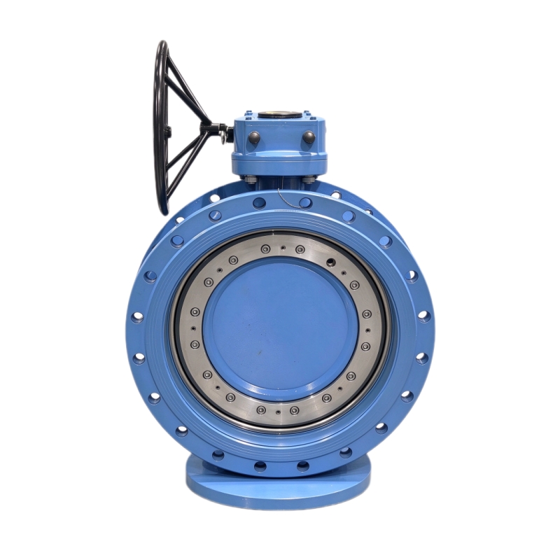
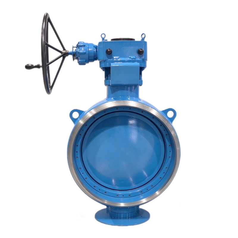
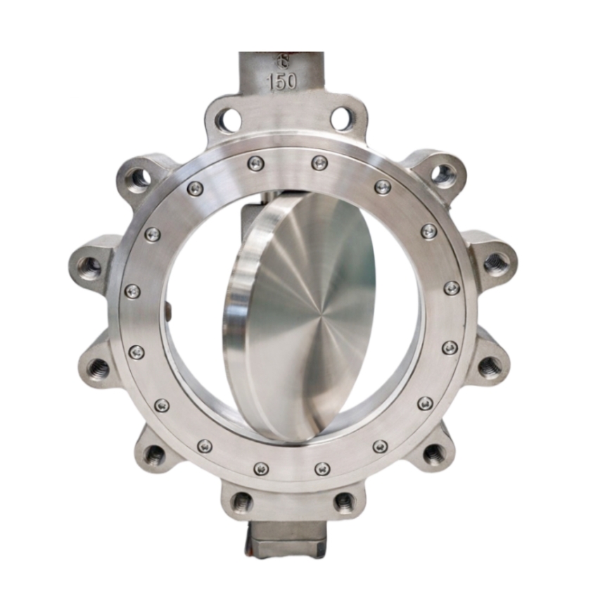
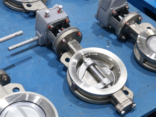
    In demanding industrial control applications, achieving "high-performance regulation" with triple-offset butterfly valves requires simultaneously overcoming three major challenges: small-opening turbulence, high-differential-pressure stability, and long-term dynamic rigidity. GEKO Fluid Control GmbH, drawing on deep expertise in fluid dynamics and precision manufacturing, has elevated the triple-offset butterfly valve from a reliable shut-off device to a precision control instrument through nine key technological innovations.   Fluid Optimization – Suppressing Disturbances at the Source Streamlined large-spherical-profile disc design optimizes the pressure distribution on the upstream face, effectively reducing vortex fluctuations at small openings.   Optimized cone half-angle and pivot radius minimize friction dead zones and enable rapid sealing-face disengagement, enhancing response sensitivity at micro-openings.   Flow Path Innovation – Balancing Pressure Reduction and Linear Control   Outlet half-orifice plate design reduces downstream vortices and lowers pressure drop, significantly improving regulation stability under high differential pressure.   Valve seat flow-guide groove design converts the inherent quick-opening characteristic into a smooth equal-percentage flow characteristic, eliminating flow surges and ensuring uniform regulation gain across the full travel range.   Severe-Service Engineering – Specialized for High Differential Pressure and Low Flow   Flow-to-open direction as standard (for blow-down, FO, and similar applications) minimizes dynamic torque fluctuations and enhances stem stability.   40–60% variable cavity reduction design in the valve seat increases flow velocity at small openings, overcoming the traditional limitation of poor controllability at low openings.   Reliability Assurance – From Torque Matching to Structural Integrity   Precise dynamic torque matching with actuator output at every opening degree ensures reliable driving force across the entire stroke.   Full-key, non-pin stem-to-disc connection provides greater load-bearing area and shear strength, ensuring rigidity and fatigue resistance under high-frequency modulation.   Anti-loosening design for sealing-face compression screws withstands high-velocity fluid impact, guaranteeing consistent sealing preload during long-term dynamic regulation.   Conclusion Through the synergistic integration of these nine precision-engineered features, GEKO has fundamentally broken the traditional perception that triple-offset butterfly valves are "only for shut-off." At GEKO, high-performance regulation represents the optimal convergence of fluid dynamics, materials science, and engineering excellence.  
    LEER MÁS
  • GEKO Valves — Providing Precise and Reliable Control Solutions for Turbine Safety
    GEKO Valves — Providing Precise and Reliable Control Solutions for Turbine Safety
    Jun 10, 2026
    In steam turbine operation systems, VV valves, BDV valves, and RFV valves are all auxiliary protection and start-up control valves. Their names are similar, and their functions are highly related. Field operators are prone to conceptual confusion, functional misjudgment, and operational errors. This article systematically clarifies the core definitions, structural principles, interlock logic, operational requirements, and key differences of these three types of valves, based on turbine design principles, unit start-stop logic, and field operation standards, providing professional technical reference for operation, maintenance, commissioning, and overhaul. GEKO Valves, with their high-precision pneumatic control technology and rigorous industrial validation, have become a trusted brand in the manufacturing and system integration of these critical valves.     I. Core Valve Definitions & Structural Working Principles (i) VV Valve (Vent Valve — HP Exhaust Vent Valve) Located on the high-pressure (HP) exhaust pipeline, this special vent and pressure relief valve leads directly to the condenser and drain flash tank. It is mainly used in intermediate-pressure (IP) start-up units to solve windage overheating issues in the HP cylinder under low load or no-inlet steam conditions, while also providing rapid pressure relief after tripping to prevent overspeed.     During IP start-up or low-load operation, the HP cylinder has little or no inlet steam, and the HP exhaust non-return valve remains closed. The blades inside the HP cylinder generate significant heat due to air friction (windage), which can easily cause overheating damage to the HP blades and casing. After a turbine trip, residual steam in the HP cylinder can leak into the vacuum state of the IP cylinder through HP-IP shaft seals, creating a risk of rotor overspeed. The VV valve quickly evacuates residual steam from the HP cylinder to avoid these risks.   It uses a pneumatically controlled, air-to-close design, consisting of an air supply, cylinder, spring assembly, and solenoid valve. GEKO Valves features an optimized high-temperature spring assembly and low-friction cylinder in this product, ensuring reliable valve opening under air failure conditions, with solenoid valve response time ≤0.5 seconds, significantly improving the timeliness of windage overheating protection.     (ii) BDV Valve (Break Drain Valve — Turbine Emergency Drain Valve) An emergency pressure relief protection valve specifically designed for combined HP-IP turbines, also known as the HP-IP shaft seal residual steam dump valve. Its core function is to quickly discharge steam that leaks past shaft seals under unit load rejection or trip conditions, eliminating the risk of turbine overspeed.     During load rejection or emergency trip of combined HP-IP units, residual steam in the HP cylinder and HP inlet pipes can leak through the HP-IP shaft seal gaps into the IP and low-pressure (LP) cylinders, creating additional driving force on the rotor. If seal teeth are worn or gaps increase, the amount of leaking steam increases, significantly raising the risk of overspeed. The BDV valve directs this residual shaft seal steam directly into the condenser, quickly releasing pressure and completely blocking the overspeed path.   It uses an electromagnetic-pneumatic linkage structure, controlled by the stroke signal of the IP control valve oil servo. GEKO Valves' BDV product adopts a redundant dual-solenoid valve design with a highly reliable pneumatic control circuit, achieving full-stroke action within 0.3 seconds after the oil servo stroke signal is triggered, effectively preventing the escalation of overspeed accidents.   (iii) RFV Valve (Reheat Warm-up Valve — HP Cylinder Reverse Warming Valve) A dedicated warm-up control valve for cold starts, used to pre-heat the HP cylinder before cold start, eliminating casing temperature differences, reducing thermal stress, and ensuring the unit meets parameters for rolling.   During a cold start, the HP cylinder casing and internal components are at very low temperatures. Directly introducing steam for rolling would create huge thermal stress, leading to casing deformation, metal cracks, and excessive shaft vibration. The RFV valve introduces auxiliary steam upstream of the HP exhaust non-return valve. The steam flows evenly through the HP cylinder and is discharged through HP inner casing drains and HP inlet pipe drains, gradually raising the casing temperature to achieve uniform warm-up.   GEKO Valves has specifically developed an RFV valve with linear regulation characteristics for these operating conditions. It uses a low-leakage seal design and anti-seize valve core, allowing precise temperature control under low flow and low differential pressure conditions, with warming rate control accuracy of ±1.5°C/h, significantly outperforming conventional products.     II. Valve Interlock Control Logic VV Valve Interlock Logic Close Interlock: Receives stroke switch signals from the four HP control valve pre-pilot valves. When all four pre-pilot valves are fully open and unit steam flow reaches 0.5% BMCR, the VV valve automatically closes. 1 minute after unit grid connection, the HP exhaust non-return valve opens, and the VV valve closes via interlock.   Open Interlock: Automatically opens during initial IP start-up and low-load windage conditions. Immediately opens via interlock after turbine trip to quickly evacuate residual HP steam.   BDV Valve Interlock Logic Close Interlock: Controlled by IP control valve oil servo stroke. When oil servo stroke ≥30mm, or when the left/right IP control valve opening reaches 15%~16% (corresponding to ~5% flow command) and the pre-pilot valve is fully open, the BDV valve automatically closes.   Open Interlock: Automatically opens when IP control valve oil servo stroke <30mm. Quickly opens via interlock under turbine trip and load rejection conditions to discharge shaft seal steam.   Pre-Pilot Valve Function Note The turbine control valve pre-pilot valve is an auxiliary valve for the main valve disc. Before the main valve disc opens, the pre-pilot valve opens first, allowing new steam to flow through the pre-pilot passage, balancing the pressure differential across the main valve. This significantly reduces the force required to open the main valve, reduces the oil servo load, and avoids difficult or stuck valve opening.   III. Field Operation & Operational Requirements Pre-Start Check: Before unit start-up and rolling, the open/close status of VV and BDV valves must be confirmed both locally and via DCS. Never start the unit with abnormal valve status.   IP Start-Up Operation: Before start-up, confirm VV and BDV valves are open. If a manual isolation valve is installed upstream of the VV valve, check that it is fully open to avoid false action due to abnormal instrument air pressure or solenoid valve failure.   Post-Valve Transfer: After completing valve transfer following IP start-up, double-check (on DEH screen and locally) that the VV valve is fully closed to prevent steam leakage or pressure abnormalities after HP cylinder admission.   Unstable Conditions: During initial start-up, commissioning, or unstable operation, do not close the manual isolation valve upstream of the VV valve, leaving an emergency path available. After stable operation, close the manual isolation valve promptly.   Post-Trip Emergency: Immediately after a trip during operation, arrange personnel to locally check and open the manual isolation valve upstream of the VV valve, while verifying BDV valve position via DCS and locally, ensuring both valves open correctly for rapid pressure relief.   Normal Start-Stop: Monitor BDV valve position feedback in real-time after the interceptor valve opens during start-up and after a trip to ensure reliable interlock action.   Cold Start Warm-Up: Before rolling during a cold start, open the RFV valve for HP cylinder reverse warming. Monitor drain paths and casing temperature rise rate. Close the RFV valve after warm-up and proceed with normal start-up.   GEKO Valve Note: Accurate valve status feedback is critical in the above operations. GEKO valves come standard with high-precision limit switches and 4-20mA position transmitters, seamlessly integrating with DCS systems to significantly reduce misjudgment risks.     IV. Key Differences & Functions of the Three Valves     Valve Core Function Control Signal Source Main Application VV Valve HP cylinder venting, addresses windage overheating, auxiliary pressure relief after trip HP control valve pre-pilot stroke, steam flow, trip signal Initial IP start-up, low-load operation, turbine trip BDV Valve Discharges shaft seal steam, core overspeed prevention IP control valve oil servo stroke, IP valve opening signal Load rejection, emergency trip, IP valve not fully open RFV Valve HP cylinder cold pre-warming, reduces thermal stress Manual control + warm-up sequence Before turbine cold start     Key Functional Distinction:   VV Valve: Focuses on daily windage overheating protection; auxiliary pressure relief after trip.   BDV Valve: Core overspeed protection valve, specifically targeting shaft seal steam leakage.   RFV Valve: Only used for cold start warm-up, no accident protection function. These three functions are not interchangeable.   GEKO Valves has developed dedicated valve series for each of these three needs, with differentiated designs from material selection (e.g., high-temperature alloy seat for VV valve), sealing structure (metal hard seal + flexible graphite for BDV valve), to actuator configuration (smart positioner optional for RFV valve), ensuring the right valve for each application.   V. Shaft Seal & Stem Leakage System Summary (Typical Plant Configuration) Main Stop Valve: 1st stage leakage → sealing steam header, 2nd stage leakage → sealing steam return header   HP Control Valve: 1st stage leakage → reheater, 2nd stage leakage → sealing steam header   IP Interceptor Valve: Only 1st stage leakage → sealing steam header   BDV Valve: 1st stage leakage → reheater, 2nd stage leakage → sealing steam header   VV Valve: 1st stage leakage → 4th extraction pipe, 2nd stage leakage → sealing steam header   HP Shaft Seal: 3rd stage leakage → 4th extraction pipe   In the above system, GEKO Valves provides matching shaft seal leak control valves and stop valves, ensuring stable leak-off pressures, reducing steam waste, and improving unit thermal economy.   VI. Core Technical Q&A 1. What are the core functions of the VV valve and BDV valve? VV Valve: During IP start-up and low-load operation, connects the HP cylinder to condenser vacuum, evacuating air from the cylinder to reduce windage heating and avoid HP blade/casing overheating. After a trip, quickly releases residual HP steam, assisting in overspeed prevention.   BDV Valve: During a trip or load rejection, quickly discharges steam that leaks from the high-pressure side through shaft seal gaps into the IP cylinder, directly cutting off additional driving force. It is a critical overspeed prevention valve.   2. Why choose GEKO valves for these critical applications? GEKO Valves has over 20 years of experience in developing specialized valves for steam turbines. Our products hold ISO 15848-1 fugitive emission certification and SIL2 functional safety certification. The VV, BDV, and RFV series have accumulated over 100,000 hours of safe operation in multiple ultra-supercritical and subcritical units worldwide, with an action success rate exceeding 99.96%. GEKO provides full-cycle technical support — from valve selection and interlock logic optimization to field commissioning — helping power plants reduce unplanned outage risks caused by valve misoperation or failure to operate.     Conclusion VV, BDV, and RFV valves each play a distinct, non-interchangeable role in turbine start-up and protection. Operating and maintenance personnel must not only master their working principles and interlock logic but also pay attention to the quality and reliability of the valves themselves. GEKO Valves, with solid technical expertise and extensive field experience, provides high-performance, high-reliability products and complete solutions for these three valve types, helping power plants achieve safer and more efficient operation.   For specific valve selection and interlock settings, please refer to the OEM design drawings and actual site conditions. GEKO Valves offers tailored technical consultation.
    LEER MÁS
  • Geko Fluid Control Technology (Changzhou) Wins Valve Supply Bid from CSSC No.703 Research Institute
    Geko Fluid Control Technology (Changzhou) Wins Valve Supply Bid from CSSC No.703 Research Institute
    Jun 08, 2026
    Geko Fluid Control Technology (Changzhou) Co., Ltd. has successfully won a competitive bidding project from the No.703 Research Institute of China State Shipbuilding Corporation Limited (CSSC). The bid award was officially announced on May 7, 2026, under project number TPJG202605070010.     The scope of supply includes ball valves, butterfly valves, globe valves, and check valves – marking an important milestone for Geko in the marine and ocean engineering sector.   German Engineering, Deep Roots in China   Geko Fluid Control Technology (Changzhou) is the core Chinese subsidiary of GEKO, a well-known European control valve manufacturer with over 60 years of history. GEKO is recognized for high-pressure and extreme-temperature resistance, with some products rated up to 60,000 psi and temperature ranges from -252°C to 649°C.     Founded in 2008 with a registered capital of 50.1 million RMB, the Chinese company is headquartered in Changzhou, Jiangsu Province. Its new factory, launched in 2022, has an annual production capacity of 120,000 units, manufacturing pneumatic/electric ball valves, butterfly valves, control valves, gate valves, globe valves, check valves, actuators, positioners, and limit switches.   Proven Track Record: National Flagship Projects     With robust product quality, Geko has participated in multiple prestigious national projects:   High-speed rail: Custom valves for CRRC high-speed train sets, passing 300,000 km road tests. Ultra-high voltage (UHV) grids: Electric explosion-proof ball valves with a 40-year design life for State Grid. Aerospace & nuclear power: Supply to rocket launch bases, Pakistan nuclear power projects, and multiple Belt and Road international projects. Domestic nuclear power: Products applied in major nuclear projects including the “Linglong One” small modular reactor. Strategic Focus: Hydrogen & New Energy   GEKO’s global strategic priority is the hydrogen energy sector, covering the entire value chain of production, storage, transport, and refueling. Core technologies include anti-hydrogen embrittlement materials, low fugitive emissions, fire and electrostatic discharge protection, and high-pressure (including liquid hydrogen) handling. Applications span hydrogen metallurgy, hydrogen power generation, hydrogen refueling stations, and fuel cell vessels/vehicles.   Leadership Perspective: Hugo Huang   Hugo Huang (Huang Wanzheng), General Manager of Geko Fluid Control Technology (Changzhou), has led GEKO’s China market expansion since 2005. He commented: *"Winning the CSSC No.703 Research Institute project is further recognition of our technical strength and delivery capability. We will continue deepening our presence in marine, nuclear, hydrogen, UHV, aerospace, and other high-end industrial valve markets, contributing to the localization of critical equipment for national strategic projects."*
    LEER MÁS
  • Geko Valve & Control Makes Early Moves in Pumped Storage Power Stations – A Promising Five Years Ahead
    Geko Valve & Control Makes Early Moves in Pumped Storage Power Stations – A Promising Five Years Ahead
    Jun 08, 2026
    As the global energy structure accelerates toward renewables, pumped storage power stations have become the most mature and economically viable large-scale energy storage solution. In response, Geko Valve & Control, a German manufacturer of industrial valves and control systems, has made early moves in the pumped storage power station sector – with a strong focus on electric ball valves for hydropower plants.     Founded in 1956 (with roots tracing back to 1946), Geko entered the Chinese market in 2005 and established a production base and sales center in Changzhou. The company has already demonstrated its reliability in critical hydropower applications, supplying valves for China's national flagship project – the Baihetan Hydropower Plant.   Tailored Solution for Pumped Storage: GKQ0350-GKV225 DN150 PN25     For pumped storage applications requiring frequent start-stop cycles, high differential pressure, bidirectional flow, and ultra-low fugitive emissions, Geko introduces the GKQ0350-GKV225 electric ball valve – featuring DN150 nominal diameter and PN25 pressure rating. This model is specifically engineered to meet the stringent demands of pumped storage power stations.   Key technologies include HVOF spraying (rocket spray process, hardness up to HRC 66–72) for superior erosion and corrosion resistance, backed by TÜV ISO15848 low-leakage certification and ISO 10497 fire safety compliance.   Looking Ahead   Geko expects strong growth over the next five years as China's 14th Five-Year Plan and subsequent initiatives roll out dozens of new pumped storage projects. The company will continue to advance its valve and control technologies for pumped storage power station systems, contributing to the next-generation power grid.   Beyond hydropower, Geko also serves high-precision and demanding industries including hydrogen energy, LNG, green methanol, nuclear power (e.g., the "Linglong One" mini-reactor), semiconductors, aerospace, and biopharmaceuticals – reinforcing its position as a forward-looking industrial valve specialist.
    LEER MÁS
  • From 550°C to 1100°C: How to Choose High-Temperature Valve Materials? – A Technical Insight from GEKO Valves
    Jun 03, 2026
    In high-temperature service conditions, the maximum allowable operating temperature of valve materials is one of the key parameters determining operational safety, stability, and service life. Due to differences in composition and microstructure, different materials have significantly different temperature limits. As a professional manufacturer of high-temperature valves, GEKO Valves, drawing on years of engineering experience, provides a systematic analysis of the three most widely used high-temperature valve material families – chrome-molybdenum steel, stainless steel, and nickel-based alloys – to help users make scientific selections based on actual operating conditions and avoid safety hazards such as seal failure and structural deformation caused by exceeding temperature limits.     Chrome-Molybdenum Steel – The Mainstream Choice for Medium-to-High Temperatures   By adding chromium and molybdenum to carbon steel, chrome-molybdenum steel significantly improves creep resistance and oxidation resistance, solving the problems of graphitization and strength degradation commonly seen in ordinary carbon steel at high temperatures. The GEKO chrome-molybdenum steel valve series covers the following common grades:   15CrMoG (equivalent to ASTM A217 WC5): Long-term temperature limit of approximately 540–550°C, suitable for auxiliary steam lines in power plants. WC9: Temperature resistance up to 593°C, widely used in main steam lines of subcritical units in thermal power plants. 2.25Cr-1Mo: Conventional design temperature rating of approximately 565–590°C, and up to 650°C with special stress-relieved treatment. It can reliably serve in medium-to-high temperature environments such as hydrogenation units. GEKO Valves applies optimized heat treatment processes to this material to further enhance high-temperature stability.     Stainless Steel – Combining Corrosion Resistance and High-Temperature Performance   Austenitic stainless steels are widely used due to their good corrosion resistance and high-temperature stability. The GEKO stainless steel high-temperature valve series offers multiple grade options:   304 / 304H: Type 304 is generally recommended for long-term use not exceeding 550°C; for higher temperatures, 304H can be selected. Suitable for high-temperature fluid control without strong corrosion. 316L: Long-term temperature resistance of approximately 550–560°C, suitable for high-temperature corrosive media containing sulfur. 321: Contains titanium, offering excellent resistance to intergranular corrosion, with a long-term temperature resistance of up to 650°C, ideal for high-temperature wet steam systems. GEKO 321 series valves have been successfully applied in multiple steam pipeline projects. 310S: Due to its high chromium and nickel content, it exhibits excellent oxidation and creep resistance, with a long-term temperature resistance of up to 700°C (in oxidizing atmospheres). Commonly used in heat treatment furnaces, incinerator exhaust systems, and other high-temperature applications. GEKO 310S valves provide reliable performance in high-temperature oxidizing environments.   Nickel-Based Alloys – The Core Material for Ultra-High Temperatures   Nickel-based alloys, relying on the excellent high-temperature stability of nickel combined with strengthening effects of chromium, molybdenum, niobium, and other elements, offer significantly higher temperature limits than chrome-molybdenum steels and stainless steels. The GEKO nickel-based alloy valve series covers the following high-end grades:   Inconel 625: Long-term continuous operating temperature of approximately 650–700°C, with short-term peaks up to 815°C. Suitable for petrochemical cracking furnace outlets, high-temperature gas systems, and similar applications. Inconel 718: Long-term temperature resistance of 650–700°C, and up to 980°C for short periods (≤1 hour), combining high-temperature strength and corrosion resistance. Haynes 282 and other high-end grades: Long-term temperature resistance covering 650–950°C. Directional solidification processes further enhance creep strength, making them suitable for extreme high-temperature applications such as nuclear power and concentrated solar power. GEKO Valves can provide customized solutions in these high-end materials. Hastelloy C-276: Long-term temperature resistance recommended within 540–590°C, with strong resistance to highly corrosive acids, suitable for medium-to-high temperature acidic fluid conditions.   Additional Sizing Considerations: Beyond Body Material – GEKO's Complete High-Temperature Sealing Solution   It is important to note that the temperature limit of a high-temperature valve is not the only criterion for selection. The corrosiveness of the medium, operating pressure, and the temperature resistance of sealing materials and seating surfaces must also be considered.   Sealing material: Flexible graphite packing has a recommended long-term temperature limit of 450–500°C in air, and up to 1600°C in inert atmospheres, making it the first choice for high-temperature sealing. GEKO high-temperature valves are standardly equipped with high-quality flexible graphite packing to ensure reliable sealing under high-temperature conditions. Seating surface material: Cobalt-based alloys (such as Stellite 6) welded on sealing surfaces can withstand temperatures above 850°C, improving erosion and wear resistance. GEKO Valves offers Stellite alloy hardfacing options based on specific service requirements. GEKO Valves Recommendation: In practice, the body material, sealing material, and seating surface hardfacing should be matched according to the temperature grade of the operating condition, forming a complete high-temperature resistance system. GEKO Valves provides a complete high-temperature solution, from material selection and sealing pairing to complete valve assembly, ensuring reliable long-term operation of your equipment in the range of 550°C to 1100°C.   Contact the GEKO Valves technical team for high-temperature valve selection advice tailored to your specific operating conditions.  
    LEER MÁS
  • What's the Difference Between O-Port and V-Port Ball Valves? – Insights from GEKO Valves
    What's the Difference Between O-Port and V-Port Ball Valves? – Insights from GEKO Valves
    Jun 02, 2026
    In industrial fluid control systems, O-port ball valves and V-port ball valves are two common types with different design focuses. Based on years of engineering experience, GEKO Valves provides a detailed comparison in terms of structural design, flow characteristics, regulating performance, shut-off capability, and more, to help you make the right choice.     1. Structural Design   O-port ball valve: The ball has a circular through-hole in the center. When fully open, the hole diameter is basically the same as the pipeline inner diameter, forming a straight flow path. GEKO O-port ball valves are precision-machined for low flow resistance and high sealing performance. V-port ball valve: The ball features a V-shaped notch. GEKO V-port ball valves allow customization of V-notch angle and size according to media characteristics, improving shearing and regulating capabilities.     2. Flow Characteristics   O-port ball valve: Approximate quick-opening characteristic. Flow increases sharply at small openings (e.g., 0°–15°), and reaches 80%–90% of full flow at around 20°–30°. Suitable for fast on/off service, poor throttling capability. V-port ball valve: Approximate equal-percentage characteristic. Flow increases smoothly and linearly with opening, designed for precise throttling. GEKO V-port ball valves maintain excellent controllability even at small openings.     3. Throttling Performance   O-port ball valve: Poor throttling performance. Flow changes drastically at small openings, making precise control difficult; prone to cavitation, vibration, and noise at medium openings. Recommended only for on/off (two-position) control. V-port ball valve: Excellent throttling performance. The V-notch provides stable, predictable flow control, and the V-shaped edge offers shearing action, making it ideal for fibrous, particulate, or slurry media. GEKO V-port ball valves deliver reliable and stable throttling performance.   4. Shut-Off Capability   O-port ball valve: Excellent shut-off capability. With soft or metal seats, it can achieve bubble-tight zero leakage. GEKO O-port ball valves are widely used in applications requiring strict shut-off. V-port ball valve: Relatively weaker shut-off capability. Theoretically, it cannot achieve the same zero-leakage performance as an O-port valve of the same size. Designed primarily for throttling, not absolute shut-off.   5. Flow Resistance   O-port ball valve: Very low flow resistance when fully open, close to a straight pipe, resulting in minimal pressure drop. GEKO O-port ball valves feature optimized flow paths for even lower energy consumption. V-port ball valve: The V-notch creates some flow resistance even when fully open, resulting in a higher pressure drop than an O-port valve.   6. Erosion & Wear Resistance (for media containing solid particles)   O-port ball valve: When switching in particulate-laden media, particles can become trapped between the ball and seat, leading to scoring, wear, or even seizure. V-port ball valve: The sharp edge of the V-notch shears fibers and solid particles, preventing clogging. Better suited for dirty media such as high-viscosity, crystallizing, particulate-laden, or slurry applications. GEKO V-port ball valves excel in wastewater, pulp, slurry, and similar tough services.   7. Typical Applications   O-port ball valve: Suitable for clean liquids and gases (e.g., water, steam, oil, natural gas). The first choice for fast and reliable shut-off. V-port ball valve: Suitable for applications requiring precise flow throttling, especially for challenging media such as pulp, wastewater, slurry, high-viscosity fluids, and crystallizing or scaling liquids. GEKO V-port ball valves are a reliable choice for control valve applications.   8. Cost   Generally, V-port ball valves are more expensive than O-port ball valves of the same size and material due to the more complex machining of the V-notch. GEKO Valves offers various configuration options to balance performance and cost – contact us for sizing recommendations.     9.How to Choose? – GEKO Valve Selection Guide     Requirement Recommended Type Reliable shut-off, zero leakage GEKO O-port ball valve Precise flow throttling GEKO V-port ball valve Clean media Either (depending on functional needs) Media containing particles, fibers, viscous or scaling substances Prioritize GEKO V-port ball valve Budget-limited and on/off only GEKO O-port ball valve   One-sentence summary: O-port ball valves are shut-off experts (tight shut-off), while V-port ball valves are throttling experts (precise control,不怕脏 – not afraid of dirty media). Your choice depends on whether you need shut-off or throttling, and the characteristics of your media.   Why Choose GEKO Valves?   German engineering standards and strict quality control Full range of O-port and V-port ball valves Customizable V-notch design for demanding applications Professional team offering free sizing and selection advice Fast delivery and comprehensive after-sales support 📞 Contact GEKO Valves today for a solution tailored to your operating conditions.  
    LEER MÁS
  • GEKO Metal Bellows Sealed Globe Valve
    GEKO Metal Bellows Sealed Globe Valve
    May 24, 2026
    GEKO: A Dedicated Valve Brand for Highly Corrosive and Highly Toxic Chemical Media   GEKO is positioned as a specialized valve brand for chemical applications involving highly corrosive and extremely toxic media. Its core product is the metal bellows sealed globe valve, designed for zero fugitive emissions, zero external leakage, and long service life. It is an ideal valve solution for highly toxic media such as chlorine, phosgene, hydrogen fluoride, and other hazardous gases.   Compared with conventional packed globe valves, GEKO bellows sealed globe valves reduce fugitive emissions by more than 100 times and offer a service life 5 to 10 times longer. Compared with other bellows valve designs, GEKO valves feature a more compact structure, easier maintenance, and lower overall operating costs.     Product Series and Technical Parameters   Main Product Series: Bellows Sealed Globe Valves T-Type Straight-Through Globe Valve This is the standard design, covering sizes from DN15 to DN600, pressure ratings from PN16 to PN160 or Class 150 to Class 2500, and operating temperatures from -20°C to +450°C. Y-Type Globe Valve The Y-pattern design offers lower flow resistance and is suitable for high-viscosity media and fluids containing particles. Angle Type Globe Valve With a 90-degree flow path, the angle type globe valve saves installation space and is commonly used for small-diameter, high-pressure applications. Chlorine Service Valve GEKO chlorine valves are designed specifically for dry and wet chlorine service. They meet European chlorine industry standards and are among the products certified by only a limited number of qualified manufacturers. These valves provide excellent corrosion resistance and zero external leakage for chlorine applications.   Materials and Pressure Ratings Valve Body: WCB carbon steel, CF8M stainless steel 316, Alloy 20, Hastelloy C for highly corrosive applications. Bellows: Multi-layer stainless steel bellows, such as 316L or 321, with a fatigue life of no less than 10,000 opening and closing cycles. Disc and Seat: Stellite 6 hardfacing, hardness HRC40–50, providing excellent wear resistance and erosion resistance.   Core Structure and Sealing Principle    Integral Structure: Three-Piece Design, Bellows Seal, No Packing Valve Body The valve body is forged or cast in accordance with ASME B16.34 and can be supplied with flanged or butt-weld ends. Bellows Assembly The multi-layer welded stainless steel bellows is connected to the valve stem at one end and to the valve body at the other end. This structure completely isolates the process medium from the atmosphere, eliminating the need for traditional packing and preventing external leakage. Valve Stem The two-section rising stem design provides reliable sealing performance. The stem is Stellite-coated, anti-rotation, and designed for low-friction operation. Disc and Seat The conical metal-to-metal sealing structure ensures tight shut-off and zero internal leakage. During opening and closing, the sealing surfaces are self-cleaned to maintain reliable sealing performance. Bonnet Flange   The bonnet flange adopts a tongue-and-groove design with a flexible graphite gasket, providing fire-safe performance in accordance with API 607.   Patented Sealing Mechanism for Zero External Leakage Absolute Isolation by Bellows The process medium is sealed inside the bellows, achieving zero fugitive emissions in compliance with TA-Luft requirements. Since there is no packing wear, the risk of external leakage is eliminated. Elastic Preload Compensation The bellows provides inherent elasticity, allowing automatic compensation for thermal expansion, contraction, and wear. This ensures stable sealing pressure during long-term operation. Conical Hard Sealing The disc and seat are precision-lapped to a micron-level finish. When closed, the metal sealing surfaces fit tightly together, achieving zero internal leakage in accordance with API 598. Anti-Torque Design   The bellows is equipped with an anti-rotation limiting structure to prevent torsional fatigue during valve operation, significantly extending service life.     Application Conditions and Performance Limits   Recommended Applications   GEKO bellows sealed globe valves are especially suitable for the following severe service conditions: Media: dry and wet chlorine, phosgene, hydrogen fluoride, hydrogen chloride, toxic gases, high-temperature steam, hot alkali, and high-temperature media containing particles. Temperature Range: -50°C to +450°C; special alloy designs can reach up to 550°C. The valve maintains stable performance under alternating hot and cold conditions. Pressure Range: Class 150 to Class 2500, or PN16 to PN160, with reliable high-pressure sealing and no internal leakage. Industries: chlor-alkali chemical plants, coal chemical industry, petroleum refining, fertilizer production, fine chemicals, and pharmaceutical manufacturing.   Applications Not Recommended Strongly abrasive media with large particles, such as high-slag black water. In such cases, a hard-seated ball valve is recommended. Low-pressure, large-diameter applications, where soft-seated butterfly valves may offer better cost performance. Very frequent opening and closing operations, because bellows have a limited fatigue life. For high-cycle services, wear-resistant ball valves are recommended.   Maintenance Guidelines and Common Faults   Key Maintenance Principles for Toxic and High-Temperature Services Never disassemble under pressure. The bellows is a thin-wall component and may rupture if disassembled under pressure. The valve must be fully depressurized to 0 MPa before maintenance. Protect the bellows from impact. The bellows has a multi-layer thin-wall structure. Hammering, squeezing, scratching, or impact damage is strictly prohibited. Soft tools should be used during disassembly and assembly. Keep maintenance records.   All maintenance steps, including disassembly, cleaning, inspection, replacement, assembly, and pressure testing, should be recorded with written notes and photos for traceability.   Common Faults and Solutions Internal Leakage or Poor Shut-Off Possible causes include coking on the sealing surface or particles stuck between the disc and seat. The valve should be disassembled, cleaned, and lapped. If the disc or seat is worn, the sealing components should be replaced. If the bellows is fatigued, the bellows assembly must be replaced. Sticking or High Operating Torque This may be caused by ash accumulation in the valve cavity, bellows deformation, or stem corrosion. The valve should be disassembled and cleaned. Deformed bellows must be replaced, and corroded stems should be derusted and lubricated with high-temperature grease. Bellows Leakage, Rare Case Possible causes include fatigue at the welded area or corrosion by the medium. The bellows should be replaced, and the material should be upgraded when necessary, such as using Hastelloy C for highly corrosive media.   Selection and Procurement Recommendations Operating Conditions First For highly toxic, highly corrosive, high-temperature, and high-pressure applications, GEKO bellows sealed globe valves are the preferred choice. For media containing particles, GEKO hard-seated ball valves are recommended. Size and Pressure Selection DN15 to DN200 and Class 300 to Class 600 are the most commonly selected and cost-effective ranges. Spare Parts Strategy   It is recommended to keep spare bellows assemblies, disc and seat sets, and bonnet gaskets of the same specifications in stock. This helps reduce maintenance downtime and overall repair costs.   Contact us for more: info@geko-union.com  
    LEER MÁS
  • Válvulas rotativas, válvulas de tapón y válvulas de mariposa de triple excentricidad GEKO resistentes a la corrosión.
    Válvulas rotativas, válvulas de tapón y válvulas de mariposa de triple excentricidad GEKO resistentes a la corrosión.
    May 20, 2026
     Posicionamiento y antecedentes de la marcaVálvulas GEKO· Fundada: 1956, Alemania• Especialidad: Válvulas rotativas de alta resistencia a la corrosión y alta fiabilidad.· Enfoque principal: cero fugas, bajas emisiones, alta seguridad• Gama de productos: Válvulas de tapón, válvulas de mariposa de alto rendimiento, válvulas revestidas de flúor.• Industrias típicas: Química, refinación, alquilación, ácidos y bases, lodos, productos químicos finosVentajas clave: Autolimpiable, sin lubricación, reparable en línea, seguro contra incendios.  Serie de productos clavea) Válvulas de tapón (válvulas de manguito)Válvula de tapón sin lubricación SleevelineEstructura: Tapón cónico + manguito de PFA/PTFE, autolimpiante.Características: Cero fugas, sin lubricación, ajustable y reparable en línea.Sellado: manguito de PFA/PTFE, bidireccionalAplicaciones: Ácidos fuertes, bases fuertes, procesamiento químico, unidades de alquilación.Mantenimiento: Sustitución del manguito sin necesidad de rectificado.  Válvula de tapón PFA totalmente revestidaEstructura: Cuerpo y tapón completamente revestidos de PFA.Aplicaciones: Corrosión extrema, halógenos, oxidantes, condiciones de alta pureza.Características: Metal totalmente aislado, cero corrosión, sin depósitos.  Válvula de tapón de alto rendimientoEstructura: asiento cónico encapsulado en PFARango de temperatura: -40 °C a 274 °CVentajas: Alta resistencia al desgaste, mayor vida útil, mantenimiento simplificado. b) Válvulas de mariposa de alto rendimientoVálvula de mariposa con asiento metálico de triple excentricidadEstructura: Sello laminado metálico de triple excentricidadClase de presión: Clase 150/300/600, PN16–PN100Sellado: ISO 5208 Grado A, cero fugas, API 607, seguro contra incendios.Aplicaciones: Alta temperatura, petróleo y gas, vapor, gas, circuitos de proceso.Características: Funcionamiento sin fricción, cierre más firme, larga vida útil. Válvula de mariposa de doble excentricidadAplicaciones: Presión media-alta, sellado bidireccional, par bajoVentajas: Sustituye a las válvulas de compuerta/cierre, es compacto y ligero.Válvula de mariposa revestida de flúorTotalmente revestido de PFA/PTFE, resistente a la corrosión.  Tecnologías básicasSellado de la manga Sleeveline: Manga de PFA/PTFE, autolimpiante, sin fugas, ajustable en línea.Sello de vástago con labio invertido: Labio invertido de PFA + precarga de resorte, doble sello dinámico y estático, bajas emisiones ISO 15848Diseño a prueba de incendios: certificado API 607, sellos a alta temperatura.Mantenimiento en línea: Sustituya el manguito, el sello o los cojinetes sin necesidad de desmontar la válvula. Materiales y sellos ComponenteMateriales comunesAplicacionesCuerpoWCB, CF8M, Alloy20, HastelloyGeneral, corrosivo, altamente corrosivoTapón/Disco316, Aleación20, recubierto de PFAResistente a la corrosión y al desgasteSello principalPFA, PTFE, TFE, metal laminadoResistente a productos químicos, a altas temperaturas y al fuego.Sello del vástagoPFA borde invertido, grafitoBajas emisiones, seguro contra incendiosRecubrimientoPFA, PTFE, FEPcorrosión extrema  Aplicaciones y modelos típicosSustancia química ácida/alcalina → Válvula de tapónRequisito extremo de corrosión/flúor → Válvula de tapón PFA totalmente revestidaRefinación/alquilación → Válvula de tapón especializadaVálvula de mariposa de triple excentricidad, resistente a altas temperaturas y al fuego, sin fugas.Lodos, aguas residuales, partículas → Válvula de mariposa revestida de flúor  Proceso de mantenimiento de válvulas GEKO1. Desmontaje: Retire el actuador → la tapa → el tapón/disco → el manguito/sello2. Piezas de repuesto (revisión completa): manguito de PFA/PTFE, sello del vástago, cojinetes, juntas tóricas, mantenimiento del actuador.3. Montaje: Alinear el tapón/disco, apretar previamente el sello de manera uniforme, seguir las especificaciones de torque, funcionamiento suave de carrera completa.4. Prueba de presión: Cuerpo 1,5 veces la presión nominal, Junta 1,1 veces, mantener ≥5 min, cero fugas, se requiere certificado de prueba.  Válvulas GEKO frente a válvulas estándar  CaracterísticaGEKOVálvula estándarSelloFunda autolimpiable, cero fugasPropenso al desgaste, fugas internasMantenimientoReparable en línea, sin necesidad de lubricación.Requiere desmontajeEsperanza de vida3–5 veces más largoCortoEmisiónCertificado de bajas emisionesEstándarResistencia a la corrosiónUltra altaEstándar ResumenEnfoque en la manga, el sellado y la alineación.Válvula de tapón: Reemplace el manguito y el sello, alinee el tapón.Válvula de mariposa: Enfoque triple excéntrico en el sello, concéntrico en el revestimiento.Todas las válvulas: Prueba de presión realizada dos veces, se emiten certificados.Corrosión extrema: Utilice PFA/PTFE auténtico, no utilice sustitutos. GEKO se especializa en válvulas rotativas resistentes a la corrosión, principalmente válvulas de mariposa de tapón y de triple excentricidad, que ofrecen cero fugas, autolimpieza, reparación en línea y bajas emisiones, ideales para operaciones químicas, de refinación y con ácidos/álcalis. El mantenimiento se centra en el reemplazo de manguitos/sellos, la alineación precisa y pruebas de presión rigurosas. Para más información, contáctanos en: info@geko-union.com 
    LEER MÁS
  • ¿Fugas internas en la válvula de nuevo? GEKO revela seis causas principales de daños en la superficie de sellado de la válvula.
    ¿Fugas internas en la válvula de nuevo? GEKO revela seis causas principales de daños en la superficie de sellado de la válvula.
    Apr 29, 2026
    En sistemas industriales como los de petroquímica, generación de energía, metalurgia y aplicaciones farmacéuticas, las fugas internas en las válvulas son un problema común que afecta la seguridad, la eficiencia y la estabilidad operativa del sistema. Una de las principales causas de las fugas internas suele ser el daño a la superficie de sellado de la válvula.Como marca especializada en válvulas industriales y soluciones de control de flujo, GEKO aprovecha años de experiencia en aplicaciones para resumir seis causas comunes de fallos en la superficie de sellado de las válvulas, lo que ayuda a los usuarios a identificar problemas con mayor precisión, optimizar la selección de válvulas y prolongar su vida útil.  1. Daños por erosiónCuando el fluido contiene partículas sólidas, como polvo de catalizador, óxido o arena, o cuando un flujo bifásico gas-líquido de alta velocidad atraviesa la válvula, la superficie de sellado se somete a impactos continuos de alta frecuencia. Esto puede provocar surcos, picaduras o desgaste lineal en zonas localizadas.Esto es especialmente común en condiciones de estrangulamiento, donde la velocidad del flujo aumenta significativamente y la superficie de sellado puede deformarse, formando marcas de flujo radiales debido a la alta velocidad del fluido. Un signo típico es la erosión lineal evidente en la dirección del flujo del medio. Recordatorio de GEKO: En fluidos que contengan partículas, con alta velocidad de flujo o en condiciones erosivas, se debe dar prioridad a los materiales de sellado y a los diseños estructurales con mayor resistencia a la erosión.  2. Deformación plástica e indentación causadas por la tensión de contacto.En el momento en que se cierra una válvula, la superficie de sellado queda sometida a una presión de contacto extremadamente alta. Si la dureza del material es insuficiente o la fuerza de cierre es excesiva, puede producirse una deformación plástica en la superficie de sellado.Los materiales blandos son propensos a sufrir abolladuras superficiales, mientras que los materiales duros pueden presentar desconchamiento localizado. Tras repetidos ciclos de apertura y cierre, la capa superficial de la junta puede endurecerse gradualmente, lo que puede provocar microfisuras y, finalmente, una delaminación. Recomendación de GEKO: Para aplicaciones de alta frecuencia o con grandes diferencias de presión, se debe prestar atención a la coincidencia de la dureza del par de sellado y al control de la fuerza de cierre para evitar fallas prematuras de la superficie de sellado causadas por sobrecarga.  3. Deformación por fluencia y ablandamiento a altas temperaturasEn tuberías de alta temperatura, como los sistemas de vapor o de aceite térmico, los materiales de la superficie de sellado de las válvulas pueden sufrir dos tipos de cambios perjudiciales.Por un lado, las altas temperaturas pueden ablandar el material, reducir su dureza y disminuir su resistencia al rayado y al desgaste. Por otro lado, bajo presión continua, la superficie de sellado puede sufrir deformación por fluencia, dañando el perfil de sellado preciso.Además, las altas temperaturas aceleran la formación de óxido. Una vez que la capa de óxido se desprende y penetra en el par de sellado, intensifica aún más la fricción y el desgaste. Recordatorio de GEKO: Para aplicaciones de alta temperatura, la selección de válvulas debe centrarse en la resistencia a altas temperaturas del material, la resistencia a la oxidación y la estabilidad del sellado. 4. Corrosión electroquímica y corrosión por hendiduraCuando se utilizan diferentes materiales metálicos en el par de sellado, como un asiento de válvula de acero inoxidable combinado con una superficie de sellado de aleación de estelita con revestimiento duro, puede formarse una celda galvánica en un medio electrolítico, lo que provoca corrosión electroquímica.Más importante aún, pueden formarse pequeñas grietas entre las superficies de sellado tras el cierre de la válvula. El fluido puede estancarse en el interior de estas grietas, generando diferencias en la concentración de oxígeno y provocando corrosión localizada, picaduras profundas o agujeros por corrosión. Si hay iones cloruro presentes, las superficies de sellado de acero inoxidable también pueden sufrir agrietamiento por corrosión bajo tensión. Recomendación de GEKO: Para medios corrosivos, se deben evaluar exhaustivamente la composición del medio, la temperatura, la concentración y la compatibilidad de los materiales para seleccionar la solución de sellado anticorrosión más adecuada.  5. Agrietamiento y descamación causados ​​por choque térmicoLas válvulas que se abren y cierran con frecuencia y rapidez, como las válvulas programadas y las válvulas de seguridad, suelen sufrir repetidos choques térmicos en la superficie de sellado.Debido a que la temperatura superficial varía más rápidamente que la del material base, pueden producirse tensiones térmicas cíclicas. Cuando la tensión supera el límite de fatiga del material, pueden aparecer gradualmente grietas de fatiga térmica en forma de malla en la superficie. A medida que las grietas se expanden y se conectan entre sí, puede producirse un desprendimiento localizado, formando un patrón de falla con apariencia de "fisuración" o "caparazón de tortuga". Recordatorio de GEKO: Para aplicaciones con grandes fluctuaciones de temperatura y funcionamiento frecuente, se deben seleccionar materiales y estructuras de sellado de válvulas con mejor resistencia a la fatiga térmica. 6. Corrosión acelerada causada por la retención del medio entre las superficies de sellado.Cuando una válvula permanece parcialmente abierta, con una pequeña fuga o mal sellada durante un período prolongado, el fluido del lado de alta presión lava continuamente la superficie de sellado, mientras que los fluidos corrosivos pueden estancarse en el lado de baja presión.En la zona estancada, las variaciones de pH, la concentración de iones y la acumulación de productos de corrosión pueden acelerar significativamente la corrosión localizada. La velocidad de corrosión puede incluso ser varias veces superior a la que se produce en condiciones normales de flujo, llegando a formar pequeñas picaduras que pueden penetrar rápidamente la superficie de sellado. Recomendación de GEKO: Durante el funcionamiento de la válvula, debe evitarse la restricción prolongada del flujo en posición parcialmente abierta o el funcionamiento con fugas existentes. La inspección periódica del sellado y el tratamiento oportuno de las pequeñas fugas internas pueden prevenir que problemas menores se conviertan en fallas graves. Conclusión de GEKOLos daños en la superficie de sellado de las válvulas rara vez se deben a un solo factor. En la mayoría de los casos, son el resultado de la combinación de erosión, desgaste, corrosión, altas temperaturas, choque térmico y condiciones de funcionamiento.Para elegir la válvula adecuada, es necesario considerar más que solo la presión nominal y el tamaño. Deben evaluarse exhaustivamente las características del fluido, el rango de temperatura, la frecuencia de funcionamiento, la presión diferencial y el riesgo de corrosión. GEKO se compromete a proporcionar soluciones de válvulas fiables, eficientes y específicas para cada aplicación a usuarios industriales, ayudando a los clientes a reducir los riesgos de fugas internas y a mejorar la seguridad y la estabilidad operativa del sistema. ¡Contáctenos para más información!
    LEER MÁS
  • ¿Cuál es el valor Cv de una válvula?
    ¿Cuál es el valor Cv de una válvula?
    Apr 24, 2026
    El coeficiente de flujo, o valor Cv, de una válvula es un indicador clave para cuantificar su capacidad de flujo. Este concepto se introdujo por primera vez en Estados Unidos, y su definición estándar es la siguiente: cuando la válvula está completamente abierta y la diferencia de presión a través de ella es de 1 psi (libra por pulgada cuadrada) a una temperatura de 60 °F (aproximadamente 15,6 °C), el valor Cv representa la cantidad de galones estadounidenses de agua limpia que fluyen a través de la válvula por minuto. Si bien esta definición puede parecer compleja, su propósito fundamental es establecer un estándar de prueba unificado, que permita comparar directamente válvulas de diferentes tipos y tamaños bajo las mismas condiciones de referencia. Esto proporciona una base estandarizada para la selección en ingeniería. En aplicaciones prácticas de ingeniería, el valor Cv se suele calcular utilizando una fórmula simplificada:Cv = Q × √(SG / ΔP)Dónde:Q es el caudal del medio (en galones por minuto, GPM),SG es la gravedad específica del medio (con el agua como referencia, donde SG = 1),ΔP es la diferencia de presión a través de la válvula (en psi). De esta fórmula se deduce que, en condiciones de presión diferencial constante, cuanto mayor sea el valor de Cv, mayor será la capacidad de flujo de la válvula. Por el contrario, conociendo Cv y el caudal, se puede calcular con precisión la caída de presión a través de la válvula, lo que facilita el control de la caída de presión en el sistema. Esta fórmula es aplicable a todo tipo de fluidos líquidos. Para fluidos gaseosos, deben tenerse en cuenta consideraciones adicionales como la compresibilidad y los efectos de la temperatura, y deben realizarse las correcciones pertinentes antes de aplicar la fórmula. Valor Cv frente a valor Kv En la práctica de la ingeniería, muchos técnicos confunden el valor Cv con el valor Kv (su equivalente en el sistema métrico internacional). Ambos valores cumplen la misma función básica, pero difieren en los estándares de prueba y las unidades utilizadas. El valor Kv se define como el número de metros cúbicos de agua limpia que fluyen a través de la válvula por hora cuando la diferencia de presión a través de la válvula es de 1 bar y la temperatura está entre 5 °C y 40 °C. La relación de conversión entre Cv y Kv es sencilla:Cv ≈ 1,17 × Kv o Kv ≈ 0,86 × Cv Por ejemplo, una válvula con un valor Cv de 100 tiene un valor Kv aproximado de 86. Comprender esta relación de conversión ayuda a los ingenieros a trabajar con documentación técnica de diferentes países y normas, evitando errores de selección debidos a diferencias de unidades. Valor Cv óptimo para la selección de válvulas Es importante destacar que un valor de Cv más alto no siempre es mejor al seleccionar una válvula. El valor de Cv debe seleccionarse en función de las características de regulación de la válvula. El rango de regulación ideal para una válvula se encuentra entre el 10 % y el 80 % de apertura. Dentro de este rango, la válvula presenta una buena linealidad y una alta precisión de control. Si el valor de Cv seleccionado es demasiado alto, la válvula permanecerá con una apertura reducida durante un período prolongado, donde pequeñas variaciones de caudal podrían causar cambios drásticos de presión, lo que provocaría inestabilidad en el control. Por otro lado, si el valor de Cv es demasiado bajo, la válvula, incluso completamente abierta, podría no ser capaz de satisfacer los requisitos de caudal máximo del sistema, creando un cuello de botella en la tubería que afecta la eficiencia general del sistema. El método de selección correcto consiste en calcular primero el valor mínimo de Cv requerido para el caudal máximo del sistema, dejar un margen del 20 % al 30 % y asegurar que la válvula opere dentro del rango óptimo de apertura del 40 % al 70 % en condiciones normales de funcionamiento. Este equilibrio garantiza una buena precisión de regulación y una alta eficiencia del caudal. Cálculo del valor Cv para válvulas en paralelo y en serie. Otro error común se refiere al cálculo del valor Cv para válvulas en configuraciones en paralelo o en serie. En el caso de válvulas en paralelo, el valor Cv total es simplemente la suma de los valores Cv individuales de cada válvula. Sin embargo, en el caso de válvulas en serie, el valor Cv total no es simplemente aditivo. Debido a la diferencia de presión acumulada en una configuración en serie, dos válvulas con el mismo valor Cv en serie darán como resultado un valor Cv total de tan solo 0,707 veces el valor Cv de una sola válvula. Esta característica es importante en diseños de derivación y aplicaciones de cierre con doble válvula, donde los errores de cálculo podrían provocar problemas de control de flujo en el sistema. Mediciones y aplicaciones de CV en el mundo real En aplicaciones reales, el valor de Cv medido puede diferir del valor nominal indicado en la placa de características de la válvula. Las pruebas de laboratorio se realizan normalmente con agua limpia y fría, mientras que las condiciones industriales reales suelen implicar vapor a alta temperatura, aceites viscosos u otros fluidos exigentes, lo que provoca desviaciones del valor nominal de Cv. Para fluidos viscosos, el valor de Cv debe corregirse mediante un factor de corrección del número de Reynolds. Para fluidos compresibles como gases y vapor, si la diferencia de presión supera el 50 % de la presión de entrada, puede producirse estrangulamiento o cavitación, lo que impide que el caudal aumente con la diferencia de presión. En estos casos, utilizar la fórmula básica sin correcciones puede generar errores de cálculo y afectar la precisión de la selección. Valor del CV a lo largo del tiempo y mantenimiento de los equipos Desde el punto de vista del mantenimiento, el valor real de Cv de una válvula varía con el tiempo debido a factores como la acumulación de incrustaciones en la tubería, el desgaste de los componentes internos y el envejecimiento de los sellos. Esto puede provocar una reducción en la capacidad de flujo de la válvula. Algunas válvulas que han estado en funcionamiento durante años pueden tener un valor real de Cv tan bajo como el 80 % del valor nominal. Por lo tanto, para aplicaciones críticas (como enclavamientos de seguridad o mezcla precisa de fluidos), es importante verificar periódicamente la capacidad de flujo de la válvula y solucionar cualquier problema de reducción de dicha capacidad para garantizar el funcionamiento estable del sistema. En ausencia de una curva Cv para la válvula, la relación Cv vs. apertura se puede aproximar en función del tipo de válvula: Las válvulas de compuerta, las válvulas de bola y las válvulas de tapón suelen tener una característica de apertura rápida,Las válvulas de globo suelen tener una característica lineal o aproximadamente lineal,Las válvulas de control (como las de globo y mariposa) pueden tener una característica de porcentaje igual o lineal, dependiendo del diseño del obturador de la válvula. Conclusión En resumen, comprender el valor Cv es fundamental para equilibrar el caudal, la caída de presión y la apertura de la válvula en un sistema. Un valor Cv demasiado elevado puede provocar inestabilidad en el control, mientras que un valor demasiado bajo puede generar cuellos de botella en el flujo. Al ajustar con precisión el valor Cv a las necesidades del sistema, es posible optimizar tanto la eficiencia energética como la estabilidad del sistema. Cuando observamos el valor Cv en la placa de características de una válvula, ya no se trata solo de un parámetro técnico frío, sino de la clave para comprender el rendimiento del sistema de fluidos y garantizar el funcionamiento óptimo de todo el sistema.
    LEER MÁS
  • ¿Por qué la válvula de mariposa de triple desplazamiento de GEKO puede redefinir el estándar de sellado de las válvulas de mariposa para temperaturas ultrabajas?
    ¿Por qué la válvula de mariposa de triple desplazamiento de GEKO puede redefinir el estándar de sellado de las válvulas de mariposa para temperaturas ultrabajas?
    Apr 22, 2026
    En los sectores industriales actuales, el sellado de válvulas en condiciones criogénicas es crucial, especialmente en industrias como el transporte de gas, la petroquímica y la química, donde el funcionamiento estable de los equipos criogénicos depende de sellos de válvula de alta calidad. La válvula de mariposa de triple excentricidad de GEKO, gracias a su diseño único y tecnología avanzada, ha redefinido los estándares de sellado para válvulas de mariposa criogénicas, garantizando un excelente rendimiento y seguridad.  ¿Por qué elegir la válvula de mariposa excéntrica triple GEKO? Estructura de sellado de metal puro, diseño verdaderamente ignífugo.La válvula de mariposa de triple excentricidad de GEKO cuenta con una estructura de sellado de metal puro que no solo soporta temperaturas extremas, sino que también previene eficazmente los riesgos de incendio. Tanto a temperaturas ultrabajas como a temperaturas elevadas, las válvulas GEKO ofrecen una seguridad inigualable, garantizando un funcionamiento estable a largo plazo.    Tasa A de fuga cero bidireccional, un tercio de la norma BS6364 a bajas temperaturas.La tecnología de sellado de GEKO garantiza la ausencia total de fugas en ambas direcciones, incluso en entornos extremadamente fríos, reduciendo significativamente las pérdidas. Además, su índice de fugas es tan bajo como un tercio del estándar BS6364, lo que mejora notablemente los beneficios ambientales y económicos de la válvula y ayuda a las empresas a reducir el desperdicio de recursos.  Junta de estanqueidad con superficie endurecida STL12/STL6, durabilidad en diversas condiciones de funcionamiento.Las válvulas GEKO utilizan superficies endurecidas con materiales STL12/STL6, lo que proporciona una excelente durabilidad y alta resistencia al desgaste en condiciones de trabajo exigentes. Esto garantiza que el conjunto de juntas mantenga un rendimiento de sellado superior durante un uso prolongado, incluso en entornos difíciles. Superficie de sellado con doble chaflán, ángulo de sellado diseñado para condiciones de funcionamiento específicas.La válvula de mariposa de triple excentricidad de GEKO cuenta con una superficie de sellado de doble bisel, cuyo ángulo de sellado está diseñado según las condiciones de funcionamiento específicas. Esto garantiza la uniformidad de la presión de sellado circunferencial. Este innovador diseño resuelve eficazmente el problema del atascamiento de la válvula en condiciones criogénicas, mejorando la precisión y la estabilidad del control de fluidos.  Diseño de junta elástica que garantiza un sellado bidireccional con bajo par de apriete y larga vida útil.El diseño de juntas elásticas de las válvulas GEKO garantiza un par de apriete bajo durante el sellado bidireccional, lo que prolonga significativamente la vida útil de la válvula. Este diseño es especialmente importante en entornos criogénicos, donde el funcionamiento frecuente reduce la frecuencia de mantenimiento y mejora la eficiencia operativa.  El vástago de válvula integral garantiza la transferencia de par y la rigidez del vástago, evitando la deformación.La válvula de mariposa de triple excentricidad de GEKO utiliza un diseño de vástago integral, lo que garantiza una transmisión de par estable y una gran rigidez del vástago, evitando deformaciones que podrían afectar al sellado. La rigidez del vástago asegura la fiabilidad durante un funcionamiento prolongado, incluso en entornos de baja temperatura.  Conexión totalmente chavetada entre el vástago de la válvula y la placa de la válvula, lo que garantiza la resistencia de la conexión y evita que se atasque.La válvula de mariposa de triple excentricidad de GEKO utiliza una conexión totalmente chavetada entre el vástago y la placa de la válvula, lo que garantiza una conexión robusta y evita que se atasque. Este diseño asegura un funcionamiento suave de la válvula, incluso durante un uso prolongado en condiciones de temperaturas extremadamente bajas. Cojinetes de soporte soldados de estelita de alta resistencia, capaces de soportar altas presiones y cargas bidireccionales.Las válvulas de GEKO están equipadas con cojinetes de soporte soldados de Stellite de alta resistencia, capaces de soportar altas presiones y cargas bidireccionales, lo que garantiza que la válvula mantenga un excelente rendimiento de sellado y estabilidad estructural en condiciones de alta presión o flujo bidireccional.  Diseño único de triple prevención de reventones, que garantiza la seguridad intrínseca en el sitio.La válvula de mariposa de triple excentricidad de GEKO cuenta con un exclusivo diseño de triple prevención de reventones, que evita eficazmente fallos en el sello o daños en la válvula que podrían provocar fugas de gas, garantizando así la seguridad de los operarios en planta. Este diseño demuestra el compromiso de GEKO con la seguridad de sus productos, asegurando la seguridad intrínseca del equipo.  Resumen de las ventajas de la válvula de mariposa excéntrica triple GEKOLa válvula de mariposa excéntrica triple de GEKO, con su avanzado concepto de diseño y tecnología de sellado de alto rendimiento, ha revolucionado los estándares de las válvulas de mariposa criogénicas. Gracias a innovaciones como la estructura de sellado de metal puro, el sellado bidireccional sin fugas, el diseño de juntas elásticas y otras características, la válvula de mariposa excéntrica triple de GEKO garantiza un excelente rendimiento de sellado, a la vez que mejora la durabilidad y la seguridad del equipo. Ya sea en alta presión, baja temperatura u otras condiciones de funcionamiento extremas, la válvula de mariposa excéntrica triple de GEKO proporciona soluciones de sellado fiables y es la opción ideal para entornos exigentes. Para más información, contáctanos en: info@geko-union.com
    LEER MÁS
  • Diferencias entre válvulas de compuerta de vástago ascendente y de vástago no ascendente
    Apr 14, 2026
    Las válvulas de compuerta de vástago ascendente y de vástago fijo son dos de los tipos más comunes en aplicaciones industriales. La principal diferencia entre ambas radica en el movimiento del vástago, y esta diferencia estructural influye en aspectos como el rendimiento de protección, los requisitos de instalación, la dificultad de mantenimiento y los escenarios de aplicación adecuados. A continuación, analizaremos estas diferencias, desde sus características principales hasta sus aplicaciones prácticas, para facilitar la elección de la válvula adecuada. 1. Diferencias estructurales y de movimiento del troncoLa característica principal de una válvula de compuerta de vástago ascendente es que el vástago se mueve hacia arriba y hacia abajo en sincronía con el movimiento de la compuerta. Las roscas del vástago quedan expuestas directamente al exterior del cuerpo de la válvula. Cuando la válvula se abre, la compuerta se eleva y el vástago se extiende hacia afuera del cuerpo de la válvula. Cuando la válvula se cierra, la compuerta desciende y el vástago se retrae dentro del cuerpo de la válvula. Al observar la longitud de la extensión del vástago, se puede determinar directamente el grado de apertura de la válvula. Por otro lado, la válvula de compuerta de vástago fijo tiene un vástago que solo gira y no se mueve verticalmente con la compuerta. Las roscas del vástago están ocultas dentro del cuerpo de la válvula y engranan con las roscas de la compuerta. La rotación del vástago impulsa la compuerta hacia arriba o hacia abajo para abrir o cerrar la válvula. Externamente, el vástago mantiene una longitud fija, por lo que no se puede observar directamente el proceso de apertura y cierre.2. Características de rendimiento y uso Indicación del estado de la válvulaLas válvulas de compuerta de vástago ascendente ofrecen una indicación visual intuitiva de su estado de apertura. El grado de apertura se determina fácilmente observando la extensión o retracción del vástago, lo que las hace especialmente útiles en situaciones que requieren una visibilidad clara del estado de la válvula, como en sistemas contra incendios, estaciones de bombeo y otras infraestructuras críticas. Esto permite a los operadores evaluar rápidamente el estado de la válvula.En cambio, las válvulas de compuerta de vástago fijo no permiten determinar su estado mediante la observación directa, ya que el vástago no se mueve verticalmente. El estado debe inferirse a partir del indicador de la válvula o de la percepción del operario durante su funcionamiento. Si el indicador no está presente o no es claro, aumenta el riesgo de un funcionamiento incorrecto, lo que incrementa la probabilidad de errores.Rendimiento de protecciónLas roscas del vástago de una válvula de compuerta de vástago ascendente están expuestas al ambiente exterior, lo que las hace más susceptibles a factores externos como el polvo, la humedad y los gases corrosivos. Con el tiempo, las roscas pueden oxidarse, atascarse o dañarse por fuerzas externas. Por lo tanto, las válvulas de compuerta de vástago ascendente ofrecen una protección relativamente menor, lo que las hace más adecuadas para interiores o entornos limpios.En cambio, las roscas de una válvula de compuerta de vástago fijo quedan completamente ocultas dentro del cuerpo de la válvula, lo que las protege del polvo y los agentes corrosivos. Su rendimiento de protección es superior, lo que la hace ideal para exteriores, entornos subterráneos o hostiles donde el fluido es corrosivo o contiene impurezas.Requisitos de espacio para la instalaciónLas válvulas de compuerta de vástago ascendente requieren suficiente espacio por encima del cuerpo de la válvula para que el vástago pueda moverse hacia arriba y hacia abajo durante su funcionamiento. Si el espacio es insuficiente, puede interferir con la correcta apertura y cierre de la válvula. Por lo tanto, estas válvulas no son adecuadas para instalaciones en espacios confinados, como bajo techos o en huecos estrechos entre equipos.Por otro lado, las válvulas de compuerta de vástago fijo solo requieren el movimiento rotacional del vástago y no necesitan espacio para el movimiento vertical. Esto las hace más compactas e idóneas para instalaciones en espacios reducidos, como tuberías subterráneas, salas de máquinas de barcos o sistemas de tuberías densamente compactadas.Dificultades y costes de mantenimientoLas roscas expuestas de una válvula de compuerta de vástago ascendente son fáciles de mantener. La limpieza y lubricación regulares previenen el agarrotamiento y la oxidación, y las reparaciones no requieren desmontar la válvula por completo. Los costos de mantenimiento son menores y la eficiencia del mantenimiento es mayor.En las válvulas de compuerta de vástago no ascendente, las roscas quedan ocultas dentro del cuerpo de la válvula, lo que dificulta el mantenimiento rutinario sin desmontarla. Si las roscas se atascan o se oxidan, es necesario desmontarla por completo para repararla. Esto aumenta la dificultad, el tiempo y los costos de mantenimiento. Medios y aplicaciones adecuadosLas válvulas de compuerta de vástago ascendente son ideales para fluidos limpios, como agua, petróleo y gas natural, donde las roscas expuestas no se obstruyen ni se corroen. Entre sus aplicaciones más comunes se incluyen plantas potabilizadoras, estaciones de bombeo, sistemas contra incendios, tuberías para fluidos limpios en la industria petroquímica y sistemas de suministro y drenaje de agua en edificios de gran altura.  Integración de válvulas de control GEKOAl considerar soluciones de válvulas de alto rendimiento como las válvulas de control GEKO, es importante destacar que ofrecen ventajas avanzadas en sellado, control y mantenimiento. Las válvulas de control GEKO se integran a la perfección con válvulas de compuerta de vástago ascendente y no ascendente, especialmente en entornos industriales donde el control preciso del flujo es fundamental. Por ejemplo, las válvulas GEKO optimizan el funcionamiento de las válvulas de vástago ascendente mediante ajustes automáticos basados ​​en datos en tiempo real, lo que garantiza que la válvula se mantenga en óptimas condiciones de funcionamiento a pesar de las condiciones ambientales adversas.Para válvulas de vástago no ascendente, las válvulas de control GEKO complementan su diseño compacto mejorando sus capacidades de control. Esto las hace ideales para aplicaciones donde el espacio es limitado, pero el funcionamiento fiable y eficiente de la válvula sigue siendo un requisito fundamental. Gracias a los avanzados sistemas de control de GEKO, ambos tipos de válvulas pueden beneficiarse del mantenimiento predictivo, lo que reduce el tiempo de inactividad y mejora la eficiencia general del sistema. La experiencia de GEKO en tecnologías de válvulas garantiza que sus sistemas de control ofrezcan un rendimiento superior tanto en entornos limpios como en entornos adversos, aportando un valor significativo a cualquier sistema de control de tuberías o fluidos. 
    LEER MÁS
1 2 3 4 5 6 7 8
Un total de 8páginas

dejar un mensaje

dejar un mensaje
Si está interesado en nuestros productos y desea obtener más información, deje un mensaje aquí y le responderemos lo antes posible.
entregar

Hogar

Productos

contacto